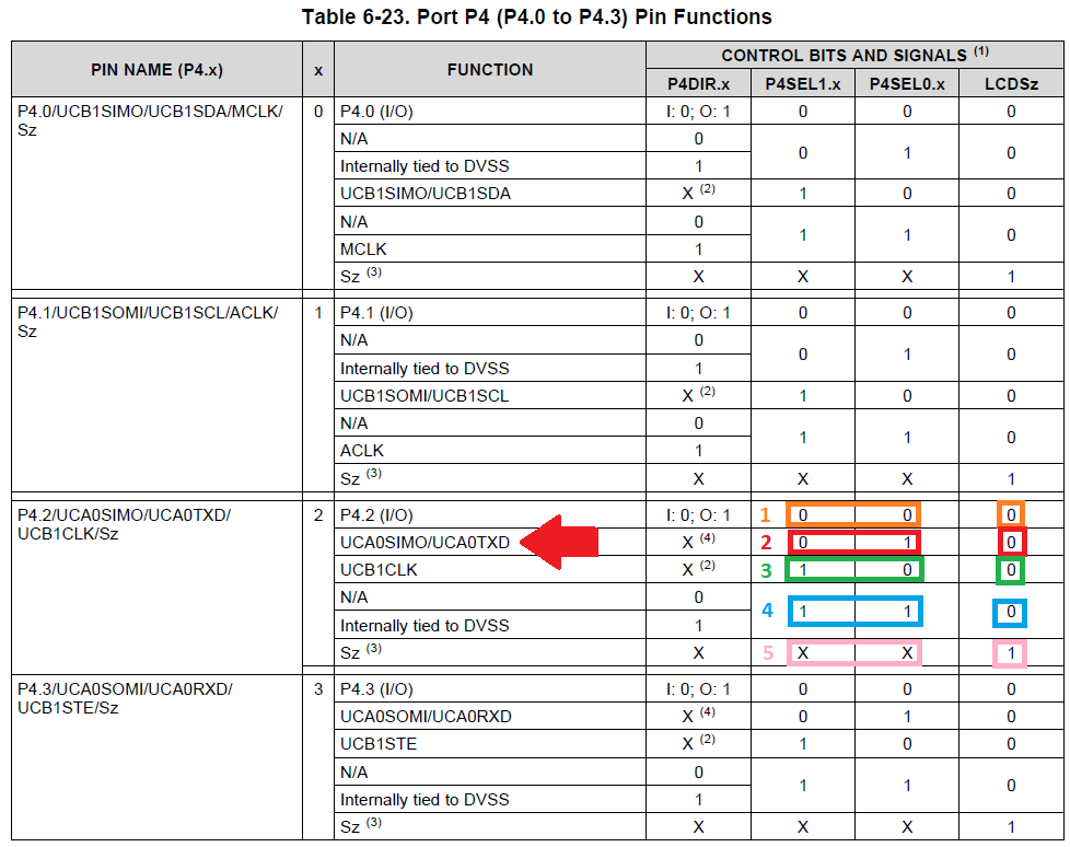
Hello,
I am using MSP430FR6928 Port 4.2 and 4.3 to perform UART TX and Rx function. The code is based on the MSP430 module library sample for eUCSI_A0. Please see the enclosed code. Voltage of the MCU power supply is 3.3V. When the program runs in debug mode, it can regularly hit the break point set in the interrupt service routine. However, the output from the TXD pin (P4.2) is constantly 1.2V when checked via an oscilloscope while I expect to see the UART frames on the pin. Please help identify the problem.
-----------------------------------------------------------------
Code
----------------------------------------------------------------
#include "driverlib.h"
uint16_t i;
uint8_t RXData = 0, TXData = 0;
uint8_t check = 0;
void main(void)
{
// stop watchdog
WDT_A_hold(WDT_A_BASE);
* Select Port J
* Set Pin 4, 5 to input Primary Module Function, LFXT.
*/
GPIO_setAsPeripheralModuleFunctionInputPin(
GPIO_PORT_PJ,
GPIO_PIN4 + GPIO_PIN5,
GPIO_PRIMARY_MODULE_FUNCTION
);
GPIO_setAsOutputPin(
GPIO_PORT_P2,
GPIO_PIN3
);
//Set DCO frequency to 1 MHz
CS_setDCOFreq(CS_DCORSEL_0, CS_DCOFSEL_0);
//Set external clock frequency to 32.768 KHz
CS_setExternalClockSource(32768, 0);
//Set ACLK=LFXT
CS_clockSignalInit(CS_ACLK, CS_LFXTCLK_SELECT, CS_CLOCK_DIVIDER_1);
//Set SMCLK = DCO with frequency divider of 1
CS_clockSignalInit(CS_SMCLK, CS_DCOCLK_SELECT, CS_CLOCK_DIVIDER_1);
//Set MCLK = DCO with frequency divider of 1
CS_clockSignalInit(CS_MCLK, CS_DCOCLK_SELECT, CS_CLOCK_DIVIDER_1);
//Start XT1 with no time out
CS_LFXTStart(CS_LFXTDRIVE_0);
* Select Port 4
* Set Pin 2, 3 to input Secondary Module Function, (UCA0TXD/UCA0SIMO, UCA0RXD/UCA0SOMI).
*/
GPIO_setAsPeripheralModuleFunctionOutputPin(
GPIO_PORT_P4,
GPIO_PIN2,
GPIO_SECONDARY_MODULE_FUNCTION
);
GPIO_setAsPeripheralModuleFunctionInputPin(
GPIO_PORT_P4,
GPIO_PIN3,
GPIO_SECONDARY_MODULE_FUNCTION
);
/*
* Disable the GPIO power-on default high-impedance mode to activate
* previously configured port settings
*/
PMM_unlockLPM5();
/*new configuration, clock = 1MHz, baud rate = 9600 bps, using oversampling to reduce the error rate*/
if ( STATUS_FAIL == EUSCI_A_UART_initAdvance(EUSCI_A0_BASE,
EUSCI_A_UART_CLOCKSOURCE_SMCLK, //using SMCLK
6, //UCBRx, 6 for 1MHz to 9600bps
8, //UCBRFx, 8 for 1MHz to 9600bps
32, //UCBRSx, 0x20 for 1MHz to 9600 bps
EUSCI_A_UART_NO_PARITY,
EUSCI_A_UART_LSB_FIRST,
EUSCI_A_UART_ONE_STOP_BIT,
EUSCI_A_UART_MODE,
EUSCI_A_UART_OVERSAMPLING_BAUDRATE_GENERATION ))
return;
EUSCI_A_UART_enable(EUSCI_A0_BASE);
EUSCI_A_UART_clearInterruptFlag(EUSCI_A0_BASE,
EUSCI_A_UART_TRANSMIT_INTERRUPT+
EUSCI_A_UART_RECEIVE_INTERRUPT
);
// Enable USCI_A0 RX interrupt
EUSCI_A_UART_enableInterrupt(EUSCI_A0_BASE,
EUSCI_A_UART_TRANSMIT_INTERRUPT+ //enable Tx
EUSCI_A_UART_RECEIVE_INTERRUPT //enable Rx
);
GPIO_setOutputLowOnPin(
GPIO_PORT_P2,
GPIO_PIN3
);
__enable_interrupt();
int counter = 0;
while (1) {
TXData = TXData + 1; // Increment TX data
// Load data onto buffer
EUSCI_A_UART_transmitData(EUSCI_A0_BASE,
TXData);
while (check != 1) ;
counter++;
check = 0;
}
}
//******************************************************************************
//
//This is the USCI_A0 interrupt vector service routine.
//
//******************************************************************************
#if defined(__TI_COMPILER_VERSION__) || defined(__IAR_SYSTEMS_ICC__)
#pragma vector=USCI_A0_VECTOR
__interrupt
#elif defined(__GNUC__)
__attribute__((interrupt(USCI_A0_VECTOR)))
#endif
void USCI_A0_ISR(void)
{
switch (__even_in_range(UCA0IV, (USCI_UART_UCTXCPTIFG | USCI_UART_UCRXIFG))) {
case USCI_NONE: break;
case USCI_UART_UCRXIFG:
RXData = EUSCI_A_UART_receiveData(EUSCI_A0_BASE);
if (!(RXData == TXData)) // Check value
while (1) ;
check = 1;
break;
case USCI_UART_UCTXIFG:
check = 1;
break;
case USCI_UART_UCSTTIFG: break;
case USCI_UART_UCTXCPTIFG: break;
}
}


