This thread has been locked.

If you have a related question, please click the "Ask a related question" button in the top right corner. The newly created question will be automatically linked to this question.

Two pwm signal with 180 degree phase shift USING msp430g2553

Other Parts Discussed in Thread: MSP430G2553

Hi,

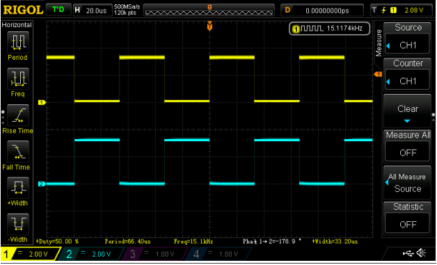
How to create two PWM signal with 180 degree phase shift.

MSP430G2553 has two timer TIMER_A0 and TIMER_A1 with three capture and compare register.

Is it possible with MSP430G2553 and if yes, what is the solution for this?

Please help me to understand the logic along with the code..

Thank you in advance..!!

  • It is possible. One capture output shall be in set/reset mode, another in reset/set mode, both shall have identical CCR register value. You shall refer to User's Guide for details

  • Thank you for the reply..!!

    Weather this is possible with single timer or i have to use two timer for this operation.?

  • One timer, with three CCRs (CCR0 for the frequency, CCR1 and CCR2 for the pulse width).
  • I have gone through the user's guide of MSP430G2553.

    This method is possible when we operate Timer in UP-DOWN Mode, where i can get the dead band also but i have NO clue as how to get this done using timer in UP MODE.

    Any suggestion is highly appreciable.!!

    I have written code for the same by using Timer_A1 in up down mode. Since i don't want the dead time stuff, i have used same duty cycle in CCR1 and CCR2.

    Can you please verify the same if possible as i don't have oscilloscope to check the output now OR can u suggest the alternate method as how to verify the same without oscilloscope at present.

    My code is given below:

    void timer_init(void)

    {

     P2DIR |= BIT1|BIT4;                          //set as output pin P2.1/TA1.1(O/P OF CCR1 Register), P2.4/TA1.2(O/P OF CCR2 Register)

     P2SEL |= BIT1|BIT4;                         //pin selected for special purpose; here for pwm

     TA1CTL |= TASSEL_2 + MC_3;       //SMCLK and up down mode

    TA1CCR0 |= 160 ;                             //pwm frequency 100 khz; DCO = MCLK = SMCLK = 16 Mhz i.e. 16M/160 = 100KHZ

     TA1CCR1 |= Duty;                              //VARIABLE Duty cycle

     TA1CCR2 |= Duty;                               // VARIBLE Duty Cycle

     TA1CCTL1 |= OUTMOD_6;               // TA1CCR1, toggle/set

     TA1CCTL2 |= OUTMOD_2;              // TA1CCR2, toggle/reset

    }

    Pin Diagram of MSP430G2553:

    NOTE: I have used TIMER_A1 in UP DOWN MODE and i want the output as shown below.

    Thank you in advance..!!

  • Thank you for the reply.!!

    What parameters will be affected by generating 2 PWM signal with 180 degree phase shift by using only 1 timer in comparison to generating 2 PWM signal with 180 degree phase shift using both the TIMER_A0 and TIMER_A1.

    Is there really any difference in max PWM width etc.

    Which one is a better option?
  • Why do you want up mode?

    Two timers running from the same clock and started at the same time will behave like a single timer with more CCRs.
  • First of all thank you so much for the reply..!

    I am stuck in this PWM generation for so long and want to come out of it asap.

    Using UP MODE is not a concern. I can use any mode. I just want to generate 2 PWM signal with 180 degree phase shift.

    NOTE: Duty cycle of PWM will vary as per application need.

    I made function for 2 PWM generation. one by using only one timer and other by using two timer, which is written below

    USING ONLY 1 TIMER_A1

    void timer_init(void)

    {

    P2DIR |= BIT1|BIT4;                                //set as output pin (P2.1 and P2.4)
    P2SEL |= BIT1|BIT4;                                //pin selected for PWM operations (P2.1/TA1.1 AND P2.4/TA1.2)

    TA1CTL |= TASSEL_2 + MC_1;            //SMCLK and up mode count till ccr register
    TA1CCR0 = 160 - 1;                             //pwm frequency 100 khz; DCO = MCLK = SMCLK = 16 Mhz
    TA1CCR1 = Duty;                               //Duty cycle 
    TA1CCR2 = Duty;                               //Duty cycle 
    TA1CCTL1 = OUTMOD_3;               //set/reset mode 
    TA1CCTL2 = OUTMOD_7;               //reset/set mode

    }

    USING 2 TIMERS, TIMER_A0 AND TIMER_A1

    void timer_init(void)

    {

    P2DIR |= BIT1|BIT6;                                //set as output pin (P2.1 AND P2.6)
    P2SEL |= BIT1|BIT6;                                //pin selected for PWM operations (P2.1/TA1.1 AND P2.6/TA0.1)

    TA0CTL |= TASSEL_2 + MC_1;            //SMCLK and up mode count till ccr register
    TA0CCR0 = 160 - 1;                             //pwm frequency 100 khz; DCO = MCLK = SMCLK = 16 Mhz
    TA0CCR1 = Duty;                               //Duty cycle 

    TA1CTL |= TASSEL_2 + MC_1;            //SMCLK and up mode count till ccr register
    TA1CCR0 = 160 - 1;                             //pwm frequency 100 khz; DCO = MCLK = SMCLK = 16 Mhz
    TA1CCR1 = Duty;                               //Duty cycle 


    TA0CCTL1 = TA1CCTL1 = OUTMOD_7;               //reset/set mode 

    }

    Can you please confirm whether both the functions are correct or am i missing something??

    Moreover as per your previous reply can i consider that using two timer is a better option in comparison to using only one timer as it will provide more range of CCR value. so, i will get more range of duty cycle variation??


    Thank you Clemens Ladisch in advance.


  • The second function uses the same output mode for both outputs, so you get a phase shift of 180° only if you start the second timer exactly 5 µs later. Otherwise, the two functions behave identically.

    Two timers do not give you more range for the duty cycle, because both use the same PWM frequency (160 ticks).

  • Hi,

    i have modified the last line of the  second function as given below

    TA0CCTL1 =  OUTMOD_3;

    TA1CCTL1 = OUTMOD_7;

    Now, as you said "Two timers do not give you more range for the duty cycle, because both use the same PWM frequency (160 ticks)."

    So, what is the advantage of using two timer instead of a single timer as two PWM signals of different duty cycle can be generated by a single timer too having three CCR. Any specific reason to use two timers??

    Thank  you..!!

  • Your two signals need the same timebase. You can of course use two timers (TA0 and TA1), both initialized with the same CCR0 value and the same value for a CCRx (1, 2, ...) of each timer, but you can also get the same result by using only one timer with it's different CCRx registers. Clemens said that you will NOT have an advantage by using two timers. So you could use CCR0 as timebase (frequency of the PWM) and CCR1 for the first and CCR2 for the second waveform's duty-cycle. One CCTLx register set to OUTMOD_3 and one to OUTMOD_7. This saves you one timer module that can be used for other things. Additionally you will have both waveforms generated by one module, so you will not have a single clock cycle mismatch in between your signals.

  • Thank you so much, i got it completely... It's better to use one timer as there is no need for synchronizing the time base. Moreover, it's a bit complex to synchronize the two time base. So, i have no other option left, but to use single timer for such application and luckily msp430g2553 has three CCR'S.
    Thank you again..!!

**Attention** This is a public forum