This thread has been locked.

If you have a related question, please click the "Ask a related question" button in the top right corner. The newly created question will be automatically linked to this question.

Regarding MSP430FR5969 Micro controller design

Other Parts Discussed in Thread: MSP430FR5969, MSP430FR6979

Hi Ti Members 

I have seen the schematic of MSP430FR5969 in some project as shown in attached images . I have 2 doubtswhich are following:-

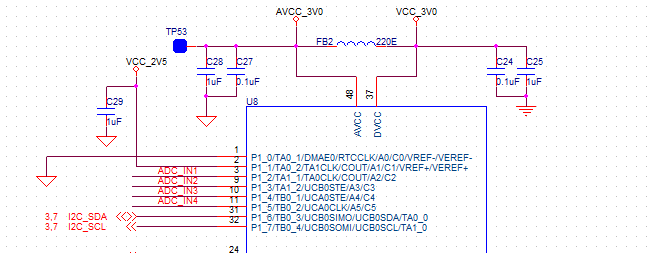
1) There they have separated AVCC and DVCC voltage with inductor (ferrite bead).So i want to know what is the purpose of this ferrite bead and how to select its value. 

2) They have also selected 2 capacitor of 1uF and 0.1uF on both VCC point (AVCC and DVCC each) so how to select these capacitor and its value.

As i,m using MSP430FR6979 for our project and wants to know how to solve that 2 above mentioned problem with this controller (i.e what value we have to connect for 2 above question and why?)

Please reply ASAP.

  • Hi Jasbeer!

    The ferrite between AVcc and DVcc shall keep the high frequency noise from the DVcc rail away from the more sensitive AVcc rail because the AVcc rail powers modules like the ADC or the analog comparators. Remember that an inductor has a higher impedance at higher frequencies. It's value should be chosen to have a high impedance at the frequencies you expect most.

    For the question why to use multiple capacitors in parallel, this might be interesting for you:

    But beside from that, the User's Guide often gives recommendations for the values that work fine. I often use 10µ + 100n in parallel.

    Dennis

  • Hi Dennis

    Thanks for you informative reply.This help me -alot to understand the basic but i have one more question:-

    1)We are using LP5907MFX-3.0/NOPB LDO to generate 3V power for MSP430FR5969 controller .Can you please tell me how much high frequency noise I can expect so that i can select my ferrite bead accordingly.
  • This is hard to say - of course one component is the operating frequency of your microcontroller because every clock cycle causes current spikes. But other parts in your system may be clocked ones as well. And square wave signals have a lot of harmonics. Often only a measurement will give you a reliable answer. Or rely on values that you find in schematics or the BOM that belongs to the schematic. Another option would be a low value resistor, followed by a capacitor, forming a RC circuit. But depending on the current draw, the resistor will cause a voltage drop, of course. You should first think if you need it at all - for example when not using any analog part of the microcontroller you can simply connect them together. Or give some attention to the routing of the different supplies. It also helps to have two independent supply rails that are connected directly at the voltage regulator. Important are decoupling capacitors close to the supply pins.

**Attention** This is a public forum