

Hi,
recently I drew a new board using the MSP430FR5872 and ordered 10x samples prints from our supplier.
I have checked the soldering, and it looks fine; voltages are allright etc etc.
I am using the CCS (v6.2.0.01631) on a MacBookPro running OS X Yosemite (v 10.10.5), and I am using the MSP-FET to JTAG the MSP.
So far, everything seems to work out; then, I wrote this small piece of code to make some LEDs blink;
int main(void)
{
    WDTCTL = WDTPW | WDTHOLD;
    _DINT();

    P6SEL0 &= ~(BIT0 | BIT1);
    P6SEL1 &= ~(BIT0 | BIT1);
    P6DIR |= (BIT0 | BIT1);
    P6OUT |= (BIT0);
    P6OUT &= ~(BIT1);

    while (1) {
    	for (volatile int i = 0; i < 0xFF; i++);
    	P6OUT ^= (BIT0 | BIT1);
    }
}
The hardware relevant for the LEDs looks as follows;
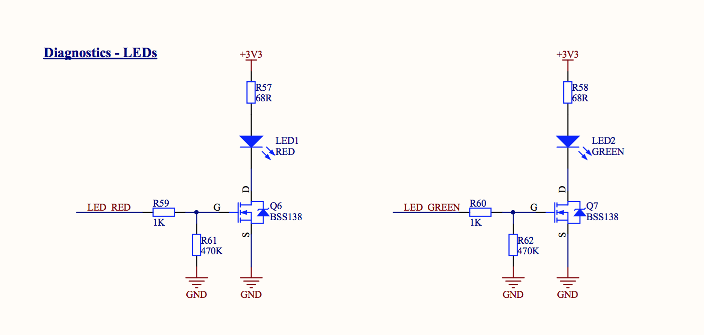
and

When I try to debug with CCS (and JTAG connector), I can run the code, or debug step-by-step, I can read the registers, however, it seems the GPIO pins 6.0 and 6.1 do not change output value.
Any idea what might be wrong ... ? Perhaps I configured something wrong with incide CCS ?
PS1 - When trying a "new" blank board (never programmed before); when I put voltage on the board, the LEDs start blinking (I assume the MSP is resetting because of invalid code, yet the LEDs blink....) Once I programmed the board once, the LEDs stay OFF; however they still "work"; when I manually put 3,3V on the mosfet gate, they light up...
PS2 - I have this problem on every board, and I triple checked the hardware connections; they seem fine...
Hope someone can help me out ?
Salvatore