


Hi All,
I have an application where I have two PWM outputs which are compliments of one another (i.e. when one is 25% the other is 75%). I am using timer A to generate both signals (there is only one timer on this chip). The frequency is 1kHz.
Here is what my code does:
1) PWM1 starts low / PWM2 starts high
2) Every 10 ms, PWM1 goes up by 0.1% while PWM2 goes down by 0.1% until they reach 100% and 0% respectively.
3) The program waits five seconds.
4) Every 10 ms, PWM2 goes up by 0.1% while PWM1 goes down by 0.1% until they reach 100% and 0% respectively. The opposite of #2.
5) The program waits five seconds.
6) Steps 2 through 5 are repeated indefinitely.
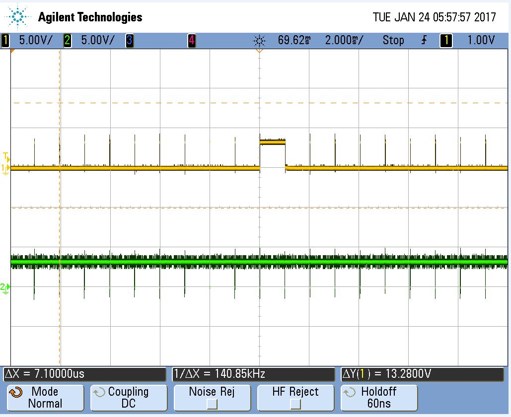
It works great with the exception of one strange issue. When the duty cycle of PWM1 goes from ~6% to the next step, the signal stays high for one cycle, then goes back to where it should be. Here is a screenshot of my scope. This also happens during turn off from ~95% to the next step.
Does anyone have any ideas on how to fix the issue?
One thing that I tried was to stop the timer before changing the value in TACCR1 and TACCR2 and starting it back up afterwards. That did not help.
Thanks in advance,
John


