This thread has been locked.

If you have a related question, please click the "Ask a related question" button in the top right corner. The newly created question will be automatically linked to this question.

MSP430F5529: Programming and communicating with PGA116

Part Number: MSP430F5529
Other Parts Discussed in Thread: PGA116

How to communicate with PGA116 from MSP430f5529 to set the gain of PGA116?

The PGA116 is given DVdd  supply from micro controller (3.3V), CS, DOUT, DIN & SCLK from corresponding micro controller pins, ENABLE pin is also kept high connecting to 3.3V.

How to send 16 bit data from master out pin of micro controller to DIN pin of PGA116?

How to access registers in PGA116?

Following program is used to initialize SPI clock, transmit and receive data


#include <msp430.h>

unsigned char MST_Data,MST_Data2,SLV_Data;
unsigned char temp;

int main(void)
{
volatile unsigned int i;

WDTCTL = WDTPW+WDTHOLD; // Stop watchdog timer

P4OUT |= 0x02; // Set P1.0 for LED
// Set P1.1 for slave reset
P1DIR |= 0x01; // Set P1.0-2 to output direction
P4DIR |= 0x02;
P3SEL |= BIT3+BIT4; // P3.3,4 option select
P2SEL |= BIT7; // P2.7 option select

UCA0CTL1 |= UCSWRST; // **Put state machine in reset**
UCA0CTL0 |= UCMST+UCSYNC+UCCKPL+UCMSB; // 3-pin, 8-bit SPI master
// Clock polarity high, MSB
UCA0CTL1 |= UCSSEL_2; // SMCLK
UCA0BR0 = 0x02; // /2
UCA0BR1 = 0; //
UCA0MCTL = 0; // No modulation
UCA0CTL1 &= ~UCSWRST; // **Initialize USCI state machine**
UCA0IE |= UCRXIE; // Enable USCI_A0 RX interrupt

P4OUT &= ~0x02; // Now with SPI signals initialized,
P4OUT |= 0x02; // reset slave

for(i=50;i>0;i--); // Wait for slave to initialize

MST_Data = 0x00; //  First byte
MST_Data2 = 0xA6;// Second byte
SLV_Data = 0x00; //

while (!(UCA0IFG&UCTXIFG)); // USCI_A0 TX buffer ready?
UCA0TXBUF = MST_Data; // Transmit first character

__bis_SR_register(LPM0_bits + GIE); // CPU off, enable interrupts
}

#if defined(__TI_COMPILER_VERSION__) || defined(__IAR_SYSTEMS_ICC__)
#pragma vector=USCI_A0_VECTOR
__interrupt void USCI_A0_ISR(void)
#elif defined(__GNUC__)
void __attribute__ ((interrupt(USCI_A0_VECTOR))) USCI_A0_ISR (void)
#else
#error Compiler not supported!
#endif
{
volatile unsigned int i;

switch(__even_in_range(UCA0IV,4))
{
case 0: break; // Vector 0 - no interrupt
case 2: // Vector 2 - RXIFG
while (!(UCA0IFG&UCTXIFG)); // USCI_A0 TX buffer ready?
SLV_Data=UCA0RXBUF;
if (UCA0RXBUF==SLV_Data) // Test for correct character RX'd
P1OUT |= 0x01; // If correct, light LED
else
P1OUT &= ~0x01; // If incorrect, clear LED

// MST_Data++; // Increment data
// SLV_Data++;
UCA0TXBUF = MST_Data; // Transmit First byte
while (!(UCA0IFG&UCTXIFG));
UCA0TXBUF = MST_Data2;//Transmit Second byte

while((UCA0STAT&BIT0)); // check transmission over
for(i = 20; i>0; i--); // Add time between transmissions to
// make sure slave can process information

break;
case 4: break; // Vector 4 - TXIFG
default: break;
}
}


I'm new to MSP programming & Thanks in advance

  • Please review Figures 1, 2, 56, and 62 as well as Table 2 of the PGA116 Datasheet to further understand the SPI sequence expected by this slave device. The CS pin must be driven low during communication and then released for the PGA116 to properly respond. Your clock phase and polarity settings are correct in accordance with Mode 1,1 but you need to make sure you understand why this is. Each read/write command requires at least 2 transmitted bytes and you only send one before going to LPM mode with the only wakeup being the RXIFG, therefore the device will never respond and the MCU cannot resume operation. Please further review the USCI SPI section of the MSP User's Guide along with the provided examples to get a better grasp of how to successfully accomplish communication. You should be using an oscilloscope or logic analyzer to evaluate your SPI communication lines to ensure that they are being controlled as expected.

    Regards,
    Ryan
  • Thank you Sir,

    CS driven low,

    Giving a write command 2A, data 11 as 2A11 and read command 6A00 (referred data sheet),

    tried to send 16 bit as two bytes one by one continuously,

    Enabled receive interrupt(If data received, goes to ISR data stored to a variable),

    after giving read command, PGA is to send a 8 bit data, PGA Data is assigned to SLV data and SLV data2   as the 8 bit data is sent after a 8 bit delay.

    but both SLV data reads 255 whatever be the data sent.

    Kindly give suggestions on sending the 16bit data commands to PGA, and receiving data


    #include <msp430.h>

    unsigned char MST_Data,MST_Data2,SLV_Data, SLV_Data2,MST_Data_r,MST_Data_r2 ;

    unsigned char temp; 

    int main(void)

    {

      volatile unsigned int i;

      WDTCTL = WDTPW+WDTHOLD;                   // Stop watchdog timer

      P4OUT |= 0x02;                            // Set P4.1 to reset/set slave

      P1DIR |= 0x01;                            // Set P1.0- to output direction

      P4DIR |= 0x02;                            // Set P4.1- to output direction

      P3SEL |= BIT3+BIT4;                       // P3.3,4 option select

      P2SEL |= BIT7;                            // P2.7 option select


      UCA0CTL1 |= UCSWRST;                      // **Put state machine in reset**

      UCA0CTL0 |= UCMST+UCSYNC+UCCKPL+UCMSB;    // 3-pin, 8-bit SPI master

                                                // Clock polarity high, MSB

      UCA0CTL1 |= UCSSEL_2;                     // SMCLK

      UCA0BR0 = 0x02;                           // /2

      UCA0BR1 = 0;                              //

      UCA0MCTL = 0;                             // No modulation

      UCA0CTL1 &= ~UCSWRST;                     // **Initialize USCI state machine**

      UCA0IE |= UCRXIE;                         // Enable USCI_A0 RX interrupt

      P4OUT &= ~0x02;                           // P4.1 set active low


      for(i=50;i>0;i--);                        // Wait for slave to initialize


      MST_Data = 0x11;                          // Write command in PGA 2A11

      MST_Data2 = 0x2A;                         // 01 is the data

      MST_Data_r=0x00;                          // Read Command in PGA 6A00

      MST_Data_r2= 0x6A;

      SLV_Data = 0x00;                          //

      SLV_Data2 = 0x00;

      while (!(UCA0IFG&UCTXIFG));               // USCI_A0 TX buffer ready?

      UCA0TXBUF = MST_Data2;               // Writing on PGA, Sending higher byte 2A

      UCA0TXBUF = MST_Data;                      // Sending 11

      while (!(UCA0IFG&UCTXIFG));               // USCI_A0 TX buffer ready?

      UCA0TXBUF = MST_Data_r2;             // Read command on PGA, Sending higher byte 6A

      UCA0TXBUF = MST_Data_r;                     // sending 00

      __bis_SR_register(LPM0_bits + GIE);       // CPU off, enable interrupts

    }


    #if defined(__TI_COMPILER_VERSION__) || defined(__IAR_SYSTEMS_ICC__)

    #pragma vector=USCI_A0_VECTOR

    __interrupt void USCI_A0_ISR(void)

    #elif defined(__GNUC__)

    void __attribute__ ((interrupt(USCI_A0_VECTOR))) USCI_A0_ISR (void)

    #else

    #error Compiler not supported!

    #endif

    {

      volatile unsigned int i;

      switch(__even_in_range(UCA0IV,4))

      {

        case 0: break;                          // Vector 0 - no interrupt

        case 2:                                 // Vector 2 - RXIFG

          while (!(UCA0IFG&UCRXIFG));           // USCI_A0 RX buffer ready

          while((UCA0STAT&BIT0));

          for(i = 20; i>0; i--);                // Add time between transmissions to

          SLV_Data=UCA0RXBUF;                   // to receive 16 bit data from slave ,

          SLV_Data2=UCA0RXBUF;                  // receive 2nd 8 byte

          break;

        case 4: break;                          // Vector 4 - TXIFG

        default: break;

      }

    }

  • You cannot write to UCA0TXBUF twice in a row without making sure that the TX buffer has been emptied and is ready for another byte. You are most likely only sending half of the expected bytes. And although you now set the CS low I do not see it returning to the high state after completing the communication sequence. You really need a visual representation of your SPI lines by using an oscilloscope or logic analyzer in order to properly debug your system.

    Regards,
    Ryan
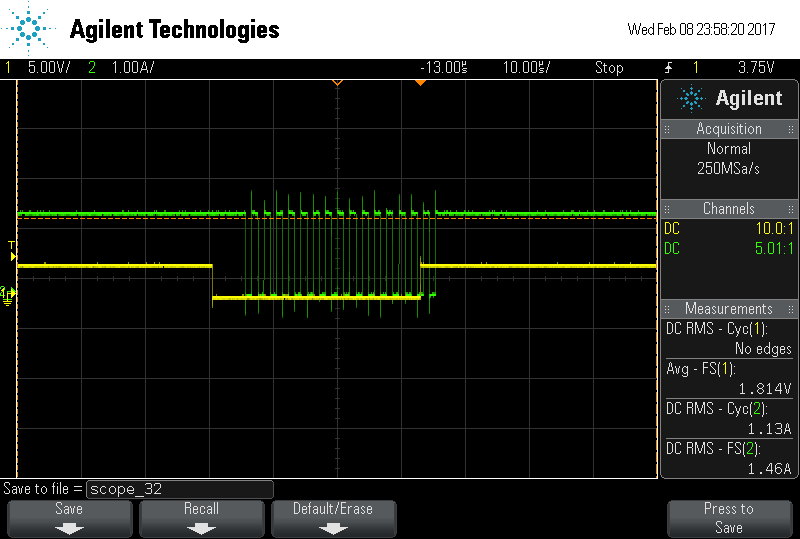
  • As told, I viewed the clock signal, data transmission and CS signal,

    As of now trying to correct transmission side signals. Now in main function I check the TX buffer ready, send the first byte, Second byte is sent in ISR only, I can view the 16 bit clock signal, and data is sent synchronised manner as shown in PGA 116 data sheet (Fig 62, Mode 1,1).

    Before sending data CS is made low and after sending two bytes and  checking transmission buffer ready, CS made high. But the CS signal is 3 clock cycles in advance of the clock pulse. Figure is attached.

    Codes in Main fuction and ISR is as below,

    int main(void)
    {
    volatile unsigned int i;

    WDTCTL = WDTPW+WDTHOLD; // Stop watchdog timer


    P2DIR |= BIT3; // chip select
    P3SEL |= BIT3+BIT4; // P3.3,4 option select
    P2SEL |= BIT7; // P2.7 option select

    UCA0CTL1 |= UCSWRST; // **Put state machine in reset**
    UCA0CTL0 |= UCMST+UCSYNC+UCCKPL+UCMSB; // 3-pin, 8-bit SPI master
    // Clock polarity high, MSB
    UCA0CTL1 |= UCSSEL_2; // SMCLK
    UCA0BR0 = 0x02; // /2
    UCA0BR1 = 0; //
    UCA0MCTL = 0; // No modulation
    UCA0CTL1 &= ~UCSWRST; // **Initialize USCI state machine**
    UCA0IE |= UCRXIE; // Enable USCI_A0 RX interrupt

    P2OUT &= ~BIT3; // Now with SPI signals initialized,
    P2OUT |= BIT3; // reset slave

    for(i=50;i>0;i--); // Wait for slave to initialize

    MST_Data = 0x2A; // Initialize data values
    MST_Data1=0x01;
    SLV_Data = 0x00; //

    while (!(UCA0IFG&UCTXIFG)); // USCI_A0 TX buffer ready?

    UCA0TXBUF = MST_Data; // Transmit first character


    __bis_SR_register(LPM0_bits + GIE); // CPU off, enable interrupts
    }

    Code under ISR

    {
    volatile unsigned int i;

    switch(__even_in_range(UCA0IV,4))
    {
    case 0: break; // Vector 0 - no interrupt
    case 2: // Vector 2 - RXIFG

    P2OUT &= ~BIT3; CS low 
    UCA0TXBUF = MST_Data;
    while (!(UCA0IFG&UCTXIFG));
    UCA0TXBUF = MST_Data1;
    while (!(UCA0IFG&UCTXIFG));
    P2OUT |=BIT3; CS high

    for(i = 20; i>0; i--); // Add time between transmissions to
    // make sure slave can process information
    break;
    case 4: break; // Vector 4 - TXIFG
    default: break;
    }
    }

    suggest  how to synchronize CS signal with clock pulses

  • The while (!(UCA0IFG&UCTXIFG)); loop does not indicate that the byte has been fully sent out on the SIMO line, only that UCA0TXBUF has been emptied and is capable of storing a new byte. This makes it possible to change the state of P2OUT before the entire byte has been sent by the USCI state machine. You should be checking the UCBUSY bit or adding an additional delay before setting CS high again. You are also using the RXIFG ISR incorrectly as it should be reserved for receiving bytes, transmission should be handled in the main function.

    Regards,
    Ryan
  • OK, but transmitting two bytes:

    while (!(UCA0IFG&UCTXIFG));

    Transmit MST data

    while (!(UCA0IFG&UCTXIFG));

    Transmit MST data1

     1)the statements in the main function sends only 8 bit data, with 8 clock pulses. Can I use for loop for sending two bytes or any other method

    2)Instead of using RXIFG ISR can I use transmit interrupt enable in main function.

    Thank you

    Vaishnavi

  • You would need to show an oscilloscope screenshot of the above code only sending one byte. You could plausibly use a TXIFG ISR to send the second byte since the flag would indicate that first byte has been sent out and that UCA0TXBUF is empty and can be populated with another byte, but this seems excessive when a simple while loop should suffice.

    Regards,
    Ryan
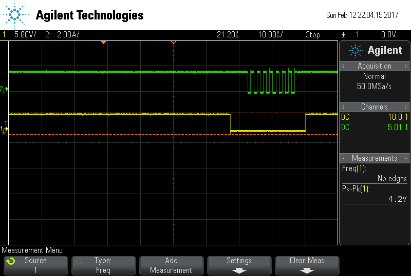
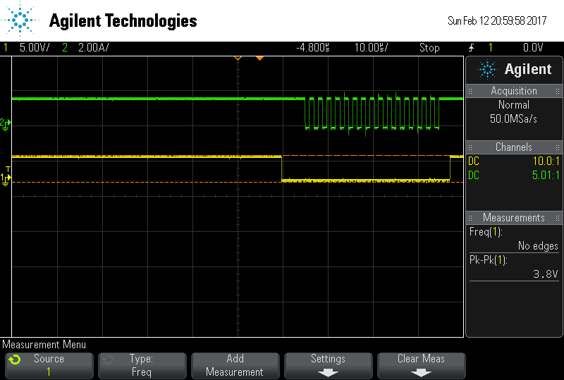
  • Dear Sir, as previously told, checking UCBUSY bit helped in correcting the CS at the end of Clock signal. I have attached the oscilloscope screenshot of sendin one byte and two byte, Now i sent the bytes through TXIFG ISR, even one byte i can send through ISR only, but the following statements is to be given in main function also, I understood like its calling ISR (pls correct if misunderstood)

    while (!(UCA0IFG&UCTXIFG)); // USCI_A0 TX buffer ready?
    UCA0TXBUF = MST_Data

  • In reply to Ryan Brown1:
    I want to send and receive data through SPI to PGA 116, Now I understood I need to send 3- 16 bit data (6 bytes) Write command , Read command and dummy 16 bit command . while sending dummy 16 bit command the PGA would send its data. (according to datasheet). (Pls correct if mis understood) To implement i used for loop with 6 count in Tx ISR.

    P1OUT &= ~BIT3;
    for(i=0; i<6; i++)
    {
    while (!(UCA0IFG&UCTXIFG));
    UCA0TXBUF = MST_Data[i];
    while (!(UCA0IFG&UCRXIFG));
    slv_Data[i]=UCA0RXBUF;
    }
    while((UCB0STAT&BIT0));
    P1OUT |=BIT3;
    -------
    Called the below statement in Main function:

    while (!(UCA0IFG&UCTXIFG)); // USCI_A0 TX buffer ready?
    UCA0TXBUF = MST_Data[0];

    Did not get any clock signal and any pulses. Suggest how this can be implemented?
  • You should not be implementing a while loop to send and receive multiple bytes while inside of the USCI ISR.

    Regards,
    Ryan

**Attention** This is a public forum