This thread has been locked.

If you have a related question, please click the "Ask a related question" button in the top right corner. The newly created question will be automatically linked to this question.

MSP430F5340: Regarding failure of device on Burst

Part Number: MSP430F5340
Other Parts Discussed in Thread: MSP-TS430RGZ48B

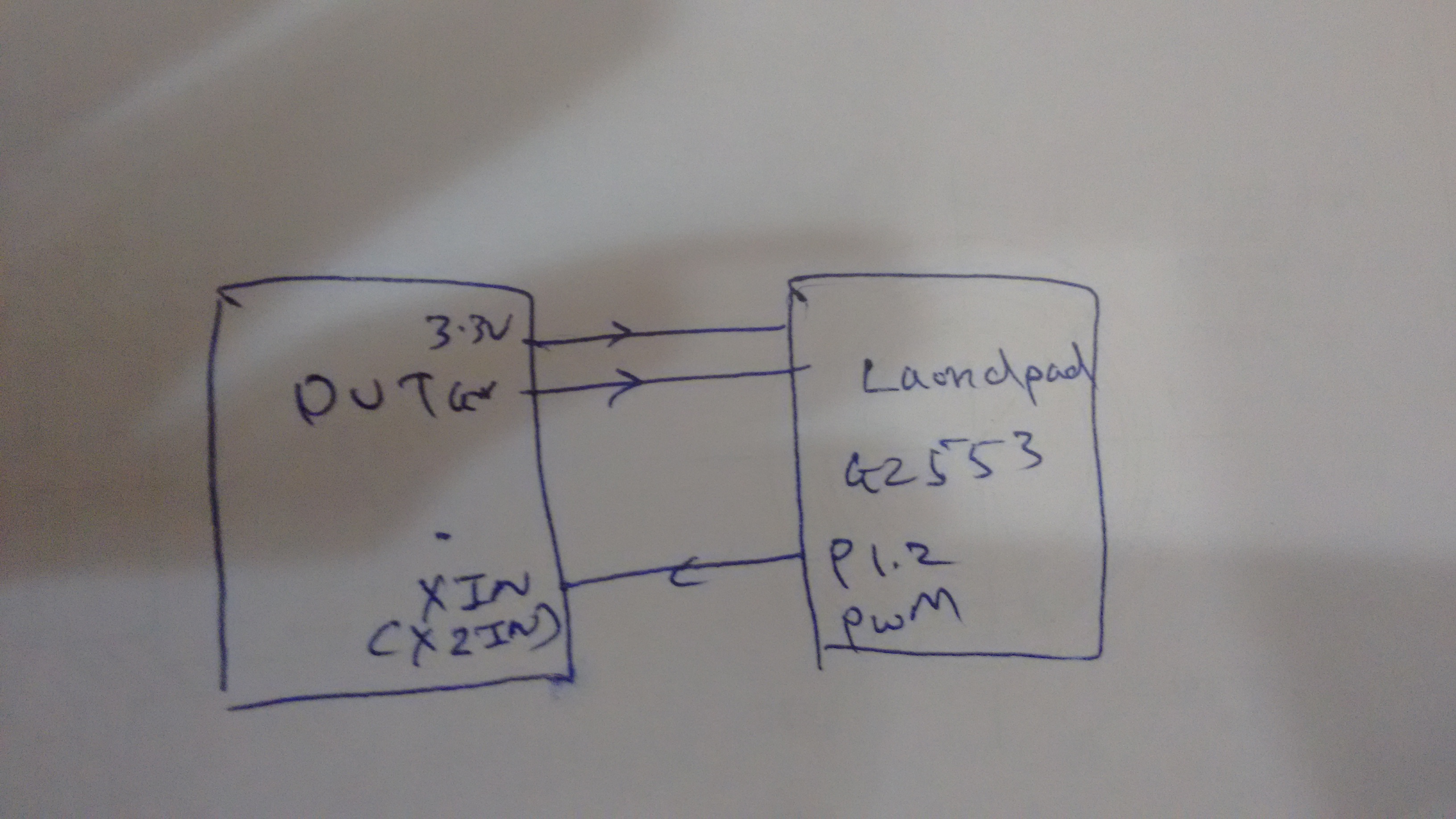
I conducted EFT on the above mentioned device and it fails at a pulse of 500V only when an external crystal is connected, but if I run the test on device (working on internal crystal) with 4KV pulse the device runs ok. 

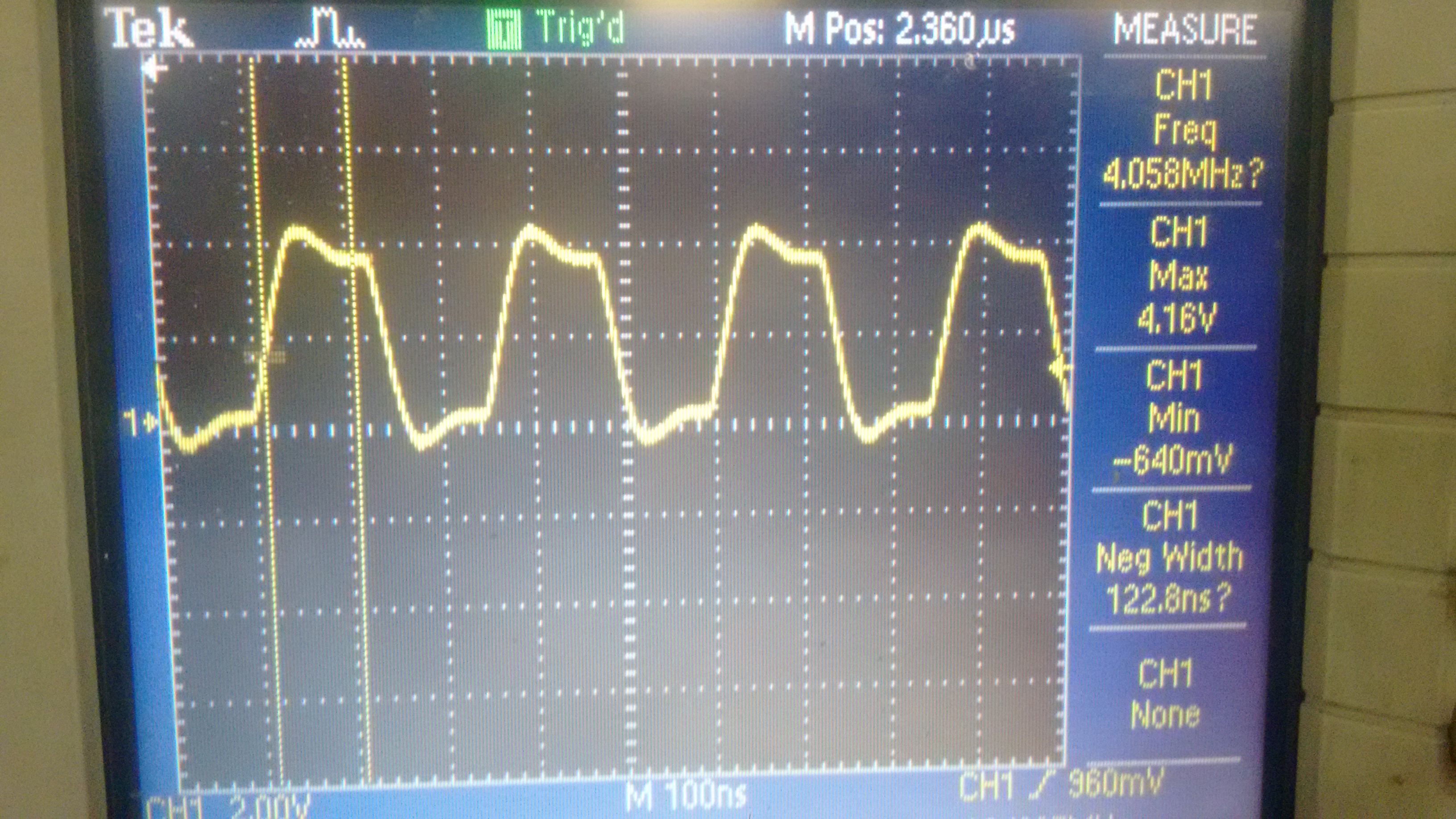
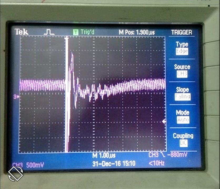
1) Is the PLL section of the device which is being affected? I see a glitch in oscillation of crystal during noise pulse and then the crystal oscillations stabilizes(during absence of noise pulse): this cycle repeats as noise pulses are running and eventually the MSP gets hanged. Is there any solution for it??

2) If I use KC5032A16.000CM0E00 as an external oscillator at 3.3V instead of crystal, will it solve my problem? And if I were to use it then how can I configure MSP for an external clock source?

3) If the above mentioned oscillator also won't solve my problem and if i were to use internal crystal (in a temperature range of -20 to 80 degree Celsius) how should I compensate the temperature drift on UART baudrate (as the DCO frequency drifts as temperature changes)?

  • What is the frequency of your crystal? XT1 is part of the Unified Clock System (UCS) and fail-safe operation is covered in Section 5.2.12 of the User's Guide and a the proper firmware should be able to handle the clock sources accordingly if XT1 fails as indicated by its fault flag. Also ensure that the maximum default drive strength (XT1DRIVE) is being used. A proper hardware design could help minimize the effects of ESD, please refer to the Crystal Oscillator Application Report (SLAA322): www.ti.com/.../slaa322c.pdf

    An external oscillator can be more dependable than a crystal, it would be selected by setting the XT1BYPASS bit. REFO is not recommended as a source for the UART as its frequency does vary by +/- 3.5 % over the full temperature range, the DCO may be steady enough so long as a baud rate is kept low enough. You could evaluate the DCO frequency at a given temperature and adjust accordingly or implement a check sum to make sure that the bytes sent were received as intended.

    Regards,
    Ryan
  • I am using an 8 or 16MHz crystal. So, I am using XT2. If I proceed with the external oscillator which I mentioned, should the following code suffice for running the device at 16MHz (using KC5032A16.000CM0E00):


    WDTCTL = WDTPW+WDTHOLD; // Stop watchdog timer

    P5SEL |= BIT2+BIT3; //P5.2,3 = XT2 IN and OUT - X2IN connected to oscillator and XT2OUT is left open

    UCSCTL6 &= ~XT2OFF; // Enable XT2

    UCSCTL3 |= SELREF_2; // FLLref = REFO

    // Since LFXT1 is not used,
    // sourcing FLL with LFXT1 can cause
    // XT1OFFG flag to set

    UCSCTL4 |= SELA_2; // ACLK=REFO,SMCLK=DCO,MCLK=DCO

    UCSCTL6 |= XT2BYPASS;

    do
    {
    UCSCTL7 &= ~(XT2OFFG + XT1LFOFFG + DCOFFG);
    // Clear XT2,XT1,DCO fault flags
    SFRIFG1 &= ~OFIFG; // Clear fault flags
    }while (SFRIFG1&OFIFG); // Test oscillator fault flag


    //UCSCTL6 |= XT2DRIVE0; // Decrease XT2 Drive according to
    // expected frequency

    UCSCTL4 |= SELS_5 + SELM_5; // SMCLK=MCLK=XT2

    UCSCTL5 |= DIVS_1; //SMCLK = MCLK/2


    1) Should i check for the fault flag in this case also?? i.e when external oscillator is used?

    2) Is there any method to check that the MSP430 is working on external oscillator and not internal one (if there is any way that the MSP automatically switches to internal source when it finds any fault on external oscillator pins). 

  • XT2DRIVE1 should be selected for 8 to 16 MHz operation. If a fault is detected for XT2 while sourcing MCLK, MCLK is automatically switched to the DCO for its clock source (DCOCLKDIV). Your DCO should therefore be initialized in case of such a situation and you will need to detect this failure using the OFIFG to determine what action to take.

    Regards,
    Ryan
  • So what you are saying is that even if I use an external oscillator, I still need to use XT2DRIVE bit!!! Is it so??

    Would the polling mechanism of OFIFG which I mentioned in my previous post (code) suffice to ensure that my device is running with reference to external clock source?

    I haven't used the Drive bit currently (for external oscillator) and I am observing that the device is switching to internal dco at 1MHz (since the device is running slow as compared to when I use a crystal of 8/16Mhz). Is the drive bit the reason for it?

  • I had forgotten that we were dealing with an external oscillator and not a crystal, in this case the XT2DRIVE bit settings do not matter. The fault flag loop will ensure that there are no fault flags occurring after initialization of the UCS, however an ISR would be useful for evaluating a fault flag that might happen during normal operation.

    When does the device switch from XT2 to the DCO? Is the XT2OFFG set at this time? Does your digital square wave input follow the parametrics defined in the Schmitt-trigger inputs section of the Datasheet?

    Regards,
    Ryan
  • Hello,
    I ordered the above mentioned external oscillator and saw its output waveform, and to my surprise, it is giving a sawtooth wave instead of a square one. Will that be okay?? Or does it require only a square wave as mentioned in the datasheet? If yes can you suggest an external oscillator which by your knowledge gives a square wave output! 
    This is the alternative one that I have found out:
    This alternative one might give a square wave as it is mentioned CMOS TTL.
    Secondly, if in the meanwhile (till the alternative arrives) I want to use the DCO as my clock (at 8MHz) and I want to implement a mechanism to change the baudrate as the temperature changes; is any menthod to do so? What if I change the DCO frequency  according to the temperature from internal sensor of MSP? Is runtime frequency change of DCO possible? And if yes, how can I do so? Will the following code lines suffice for runtime DCO frequency change:

    __bis_SR_register(SCG0); // Disable the FLL control loop
    UCSCTL2 = FLLD_1 + 254;
    __bic_SR_register(SCG0); // Enable the FLL control loop

    Or the entire mechanism is required!!!

    Thanks and Regards

    Chinmay

  • Hello Chinmay,

    The Datasheet specifies that a digital square wave must be used, but it may work so long as the Schmitt-trigger input parameters are properly followed. Given that you are able to measure the device's internal temperature, how would you know by what amount to alter the FLLN bits of UCSCTL2 to calibrate the DCO at 8 MHz? The TLV does not contain any DCO calibration values and there is no steady external reference available to measure the DCO frequency with. If you provided an external crystal oscillator at XT1 then you would be able to calibrate the DCO in a similar fashion as shown in the msp430g2xx3_dco_flashcal.c example. You can evaluate the DCO shift with temperature from a few devices and make educated guesses with a look-up table, but DCO drift varies from device to device so you may still get UART errors on some MCUs.

    Regards,
    Ryan
  • At first I checked the device with the sawtooth oscillator connect as external source, then the device is switching to default DCO. The sawtooth voltage goes from 600mV (min) and 2.4V (max), the min of the sawtooth is very close to the minimum specified in the datasheet which is 750mV. Is this the reason that the device isn't accepting the sawtooth signal?
    Then I generated a square wave of 4MHz (0 to 3.3V going) from MSP Launchpad and i observed the same happening. The device is still switching to internal source. What might be the reason?

    Code:

    WDTCTL = WDTPW+WDTHOLD; // Stop watchdog timer
    P5SEL |= BIT2 + BIT3; //P5.2,3 = XT2 IN and OUT
    UCSCTL6 &= ~XT2OFF; // Enable XT2
    UCSCTL3 |= SELREF_2; // FLLref = REFO
    // Since LFXT1 is not used,
    // sourcing FLL with LFXT1 can cause
    // XT1OFFG flag to set
    UCSCTL4 |= SELA_2; // ACLK=REFO,SMCLK=DCO,MCLK=DCO

    UCSCTL6 |= XT2BYPASS;

    do
    {
    UCSCTL7 &= ~(XT2OFFG + XT1LFOFFG + DCOFFG);
    // Clear XT2,XT1,DCO fault flags
    SFRIFG1 &= ~OFIFG; // Clear fault flags
    }while (SFRIFG1&OFIFG); // Test oscillator fault flag // IF I remove XTL1OFFG and DCOOFFG then the device gets stuck at this point


    //UCSCTL6 |= XT2DRIVE0; // Decrease XT2 Drive according to
    // expected frequency

    UCSCTL4 |= SELS_5 + SELM_5; // SMCLK=MCLK=XT2
    UCSCTL5 |= DIVS_1;
  • Please provide your debugging efforts, is the code getting stuck inside of the fault flag loop or does it get to the main while loop? What are your LaunchPad connections? View the UCS register contents inside of your debugger and confirm that they are set as expected.

    Regards,
    Ryan
  • 1) The code gets stuck inside the fault loop when I use the following lines:

    do
    {
    UCSCTL7 &= ~(XT2OFFG);
    // Clear XT2,XT1,DCO fault flags
    SFRIFG1 &= ~OFIFG; // Clear fault flags
    }while (SFRIFG1&OFIFG); // Test oscillator fault flag\

     XT1LFOFFG + DCOFFG - when i add these two lines then it moves forward to the main function but the default DCO is initialized.

    2) I have generated a PWM from launchpad and have given it to DUT. The supply and GND from the DTU are given to the launchpad so that they operate on same ground levels. When I see the PWM on an oscilloscope then I see a very bad pulse. Is this the reason that the device (DUT) isn't getting clocked externally!


    3) If external oscillator doesn't workout very well, is there any way that I can control baud rate with respect to temperature. Moreover, can I set the baud rate registers runtime without using the UART reset bit? It is advised to use reset in the datasheet, but as per my observation when I use reset and also re-enable RXIE (while changing baud rate runtime in main), the MCU misses received bytes.

    4) If I change the DCO frequency runtime by changing the multiplication factor N what minimum part of code is required to do so?

  • 1) You can't just clear XT2OFFG while evaluating the OFIFG. What do you mean by "the default DCO is initialized" and how do you know that MCLK and SMCLK are not sourced by XT2?
    2) Pulse maximums should not approach 4 V if the LaunchPad 3.3 V rails is being supplied to the DUT.
    3) We've already discussed how you will not be able to reliably control the baud rate using the DCO as a source with varying temperature. And it is required to hold the UART in a reset state while changing the baud rate control registers.
    4) This would require disabling the FLL control loop, setting the multiplication factor of UCSCTL2 (and possibly the DCORSEL range from UCSCTL1), and re-enabling.

    Please provide a schematic and layout image of your DUT and, if possible, test your system with a MSP-TS430RGZ48B EVM instead.

    Regards,
    Ryan

**Attention** This is a public forum