This thread has been locked.

If you have a related question, please click the "Ask a related question" button in the top right corner. The newly created question will be automatically linked to this question.

MSP430FR69891: No Interrupt from USCIA0 Interface in SlaveMode with UCCKPH=1

Part Number: MSP430FR69891
Other Parts Discussed in Thread: MSP430FR6989

Hello

I am using the LaunchPad Eval Kit with the MSP430FR69891 uP.

I want to use the SPI Interface USCIA0 in slave mode, 4 pin mode active high, with clock phase flag UCCKPH=1 enabled

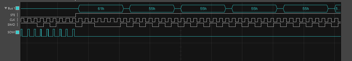
I have the UCA0IE set and also GIE is set. On the Logic Analyzer i can see that the UCA0STE pin goes high, the clock is working the data (SIMO) is correct but the interrupt gets not activated.

I could observe that if i don't set the UCCKPH (UCCKPH=0) the interrupts are working and also if i do the configuration of the SPI interface with the UCSWRST=0 (which is incorrect) it is also working,

I am using CCS 7 with GNU compiler (GNU v6.2.1.16 DOMNIUM Technologies Limited)

Here my configuration:

void initializeUca0Spi(void)
{
    // Configure USCI_A0 for SPI operation
    UCA0CTLW0 = UCSWRST;                      // **Put state machine in reset**
#if (RX_MODE == 1)
    UCA0CTLW0 |= UCSYNC | UCMSB | UCCKPH | UCMODE_1;
#else
    UCA0CTLW0 |= UCSYNC | UCMSB | UCCKPH;
#endif

    UCA0CTLW0 &= ~UCSWRST;
#if (RX_MODE == 1)
    UCA0IE |= UCRXIE;
    __no_operation();
#endif
}

any ideas?

Thanks in advance

  • Hello Claudio,

    What master device are you using and what are its clock configurations (phase and polarity)? Have you considered changing the clock polarity (UCCKPL) when you change the phase? When the interrupts do work, do you receive the correct data? If so then your MSP430FR6989's SPI configuration appears to be correct and there would not appear to be an issue. You should check the eUSCI register inside of the CCS debugger to make sure they are as expected, they are most likely not being modified correctly when UCSWRST is not set. Please provide the logic analyzer screenshots you referred to as well.

    Regards,
    Ryan
  • I am using a transceiver chip which acts as SPI master with clock rate 9600. It does activate the slave after a sync word has been detected. No i didn't change the clock phase because it should be like this (UCCKPH=1, UCCKPL=0). It is also listed in the MSP430FR6.. family guide.

    I get the corret data if i do not set the reset flag while configuring the interface but i have no trust in this solution because it is not the correct way.

    Best regards

    claudio

  • Just so we are on the same page, the master clock is inactive low and data is captured on the first UCLK edge/changed on the second? And you use UCCKPL = 0 and UCCKPH = 1 in the logic analyzer screenshot but do not get an interrupt? Have you tried manually controlling the STE pin or used 3-wire mode? There are no SPI USCI errata to be aware of regarding this behavior.

    Regards,
    Ryan
  • Yes exactly. I have tried to manually control the STE pin which resulted in no different behaviour. I also tried 3-pin mode which works basically (the interrupt routine is called), but then i have no timing information directly from the SPI interface and so far i did not manage to get the right synchronization via the port interrupt.

    best regards

    Claudio

  • This would appear to be a timing issue involving the STE pin, have you checked all of the specifications from Table 5-20 & Figure 5-18 of the Datasheet and confirmed that no specifications are violated? What is happening before the STE pin goes high? I see pulses on the SOMI line and the CLK is being driven before the MSP430 slave is set to an active state.

    Looking further into device errata documentation I found an instance where using the USCI 4-pin SPI slave mode with UCCKPH = 1, when data is loaded in the transmit buffer (1) before STE becomes inactive and (2) while a falling clock edge occurs on UCLK while STE is inactive, will cause the UCxTXIFG to become erroneously set. Writing to the transmit buffer will overwrite its current contents causing an unintended overwrite and therefore data in the transmit buffer can be lost under these conditions. There is unfortunately no workaround and customers are advised to not use 4-pin SPI slave mode with UCCKPH = 1 if the errata is encountered. You issue could be of a similar nature to this even though it is not documented in the FR6989 erratasheet.

    Regards,
    Ryan
  • For me the problem is solved. I could manage to reconfigure the SPI Master and change clock polarity, so therefore i can avoid setting the UCCKPH flag and instead set the UCCKPL flag for now. Probably I will try to find out the real problem some other time.

    Many thanks to you.

    Perhaps I will find an update on the errata sheet in some time;)

    Best regards

    Claudio

  • Hi Claudio,

    why are you using UCCKPH=1?

    Your picture will show a UCCKPL=1 and UCCKPH=0 signal for your supplied clock.

    Best regards,

    Peter Weber

**Attention** This is a public forum