Tool/software: Code Composer Studio
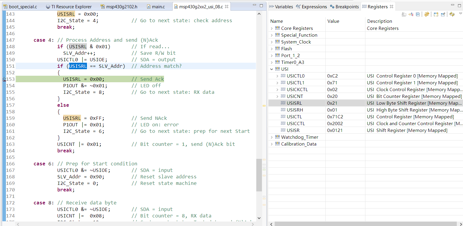
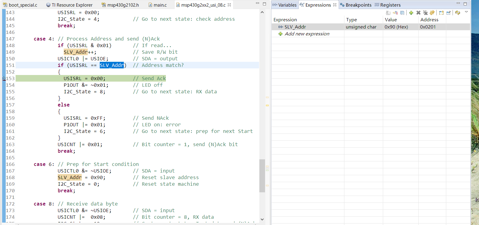
I'm using USI as an I2C slave receiver, I can not get the right data in the USISRL register.the source code is the example msp430g2xx2_usi_08.c in TI Resource Explorer.
I can enter the I2C start interrupt and I2C receive interrupt correctly.
I paste the picture of the I2C bus waveform and the USI registers in the end.
Thanks!
#include <msp430.h>


char MST_Data = 0; // Variable for received data
char SLV_Addr = 0x90; // Address is 0x48<<1 for R/W
int I2C_State = 0; // State variable

int main(void)
{
WDTCTL = WDTPW + WDTHOLD; // Stop watchdog
if (CALBC1_1MHZ==0xFF) // If calibration constants erased
{
while(1); // do not load, trap CPU!!
}

DCOCTL = 0; // Select lowest DCOx and MODx settings
BCSCTL1 = CALBC1_1MHZ; // Set DCO
DCOCTL = CALDCO_1MHZ;

P1OUT = 0xC0; // P1.6 & P1.7 Pullups
P1REN |= 0xC0; // P1.6 & P1.7 Pullups
P1DIR = 0xFF; // Unused pins as outputs
P2OUT = 0;
P2DIR = 0xFF;

USICTL0 = USIPE6+USIPE7+USISWRST; // Port & USI mode setup
USICTL1 = USII2C+USIIE+USISTTIE; // Enable I2C mode & USI interrupts
USICKCTL = USICKPL; // Setup clock polarity
USICNT |= USIIFGCC; // Disable automatic clear control
USICTL0 &= ~USISWRST; // Enable USI
USICTL1 &= ~USIIFG; // Clear pending flag
__enable_interrupt();

while(1)
{
LPM0; // CPU off, await USI interrupt
__no_operation(); // Used for IAR
}
}

//******************************************************************************
// USI interrupt service routine
//******************************************************************************
#if defined(__TI_COMPILER_VERSION__) || defined(__IAR_SYSTEMS_ICC__)
#pragma vector = USI_VECTOR
__interrupt void USI_TXRX (void)
#elif defined(__GNUC__)
void __attribute__ ((interrupt(USI_VECTOR))) USI_TXRX (void)
#else
#error Compiler not supported!
#endif
{
if (USICTL1 & USISTTIFG) // Start entry?
{
P1OUT |= 0x01; // LED on: sequence start
I2C_State = 2; // Enter 1st state on start
}

switch(I2C_State)
{
case 0: // Idle, should not get here
break;

case 2: // RX Address
USICNT = (USICNT & 0xE0) + 0x08; // Bit counter = 8, RX address
USICTL1 &= ~USISTTIFG; // Clear start flag
USISRL = 0x00;
I2C_State = 4; // Go to next state: check address
break;

case 4: // Process Address and send (N)Ack
if (USISRL & 0x01) // If read...
SLV_Addr++; // Save R/W bit
USICTL0 |= USIOE; // SDA = output
if (USISRL == SLV_Addr) // Address match?
{
USISRL = 0x00; // Send Ack
P1OUT &= ~0x01; // LED off
I2C_State = 8; // Go to next state: RX data
}
else
{
USISRL = 0xFF; // Send NAck
P1OUT |= 0x01; // LED on: error
I2C_State = 6; // Go to next state: prep for next Start
}
USICNT |= 0x01; // Bit counter = 1, send (N)Ack bit
break;

case 6: // Prep for Start condition
USICTL0 &= ~USIOE; // SDA = input
SLV_Addr = 0x90; // Reset slave address
I2C_State = 0; // Reset state machine
break;

case 8: // Receive data byte
USICTL0 &= ~USIOE; // SDA = input
USICNT |= 0x08; // Bit counter = 8, RX data
I2C_State = 10; // Go to next state: Test data and (N)Ack
break;

case 10:// Check Data & TX (N)Ack
USICTL0 |= USIOE; // SDA = output
if (USISRL == MST_Data) // If data valid...
{
USISRL = 0x00; // Send Ack
MST_Data++; // Increment Master data
P1OUT &= ~0x01; // LED off
}
else
{
USISRL = 0xFF; // Send NAck
P1OUT |= 0x01; // LED on: error
}
USICNT |= 0x01; // Bit counter = 1, send (N)Ack bit
I2C_State = 6; // Go to next state: prep for next Start
break;
}

USICTL1 &= ~USIIFG; // Clear pending flags
}