This thread has been locked.

If you have a related question, please click the "Ask a related question" button in the top right corner. The newly created question will be automatically linked to this question.

MSP430G2433: Can MCU be reset taking reset pin low, while Vcc is still above 1.8V

Part Number: MSP430G2433

We have an issue with the MSP430G2433.  When its Vcc voltage is slowly decreasing (it is driven by a 3.3V LDO which follows its input voltage, coming from a slowly discharging battery), if we get into deep discharge (i.e., the input to the LDO goes under 1.7V or so), in the MCU-Vcc 1.5-1.6V range the MCU does NOT reset when we get back to increasing the MCU-Vcc (via charging the battery). This is not happening on all the MCUs some of them get POR if we increase Vcc to 3.3V and hold it for an hour at that Vcc.   

Can we reset MCU by driving Reset pin low? Currently RESET pin is externally pulled up to Vcc.

I am using watchdog timer to reset MCU when it reaches below 1.8V but seems like its not working either.

Please suggest some solutions.

  • Hi,

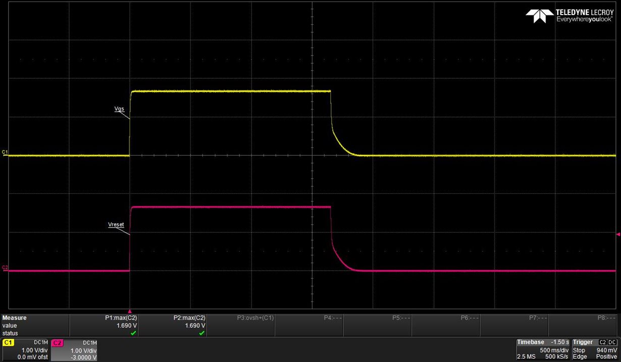
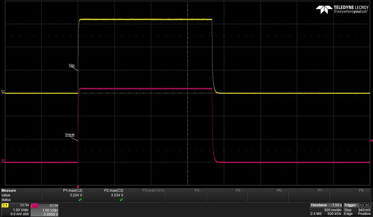
    can you please share a scope shot of the DVCC+RST pin in the power down/up scenario.
    Also interesting is the frequency you run the device during power down? Do you ensure that you will not violate the frequency vs. supply specification which can lead to unpredictable behavior?
  • Dietmar,

    Thanks for your reply.
    The frequecy is set as below:
    BCSCTL1= CALBC1_8MHZ; // System Clock Settings
    DCOCTL = CALDCO_8MHZ; // use calibrated 8MHz settings

    The first snapshot is taken when Battery voltage is 3V and 2nd when Vbat is 6V. Battery feeds to voltage regulator which feeds to Vcc of MCU.
  • Hi,

    thanks for posting the information. According to your DCO setting I have to tell you that you operate the part out of spec. If you operate the DCO with 8 MHz it is not allowed to go below 2.2V. As you can see below.

    So I recommend that you somehow detect voltage drop below 2.2V with onboard ADC and go into LPM or at least decrease frequency to follow device specification. If this does not help please let me know.

    Best regards,
    Dietmar

  • Hello Dietmar,
    Thanks for your immediate response. Please assist me how can I use LPM as we have complicated state machine for our application. Here are the details:
    1. Here is the system clock details that we use in our Micro initialization routine:
    BCSCTL1= CALBC1_8MHZ; // System Clock Settings
    DCOCTL = CALDCO_8MHZ; // use calibrated 8MHz settings
    BCSCTL3= LFXT1S_2; // System Clock Settings Watchdog

    2. We use Watchdog timer using ACLK and reset watchdog timer every now and then within different routines using WDTCTL = WDT_ARST_1000;

    3. We use Timer 1 in SMCLK in up mode for driving PWMs and Timer 0 in continuous mode as housekeeping timer.

    //Timer 0 Initialization
    TA0CCR1 = 50000;
    TA0CCTL1 = CCIE; // CCR0 interrupt enabled
    TA0CTL = TASSEL_2 + MC_2 + TAIE; // SMCLK, contmode

    //Timer 1 Initialization
    TA1CCR0 = 159; // PWM Period approx 50KHz (160-1=159)
    TA1CCR2 = 4; // CCR1 PWM duty cycle
    TA1CCTL2= OUTMOD_7; // CCR1 reset/set
    TA1CTL = TASSEL_2 + MC_1; // SMCLK, Up Mode

    4. We also have port interrupt that on port 2 for rising and falling edge detect.

    According to your recommendation, we do have a provision to detect voltage drop below 2.2V.
    Please recommend:
    1. Which LPM should I use and how can I implement that.
    2. I am Ok to shutdown SMCLK below 2.2V and wait on port interrupt to occur to get out of LPM. How can I implement this?
    3. I have watchdog timer on ACLK. How can I handle this when entering and exiting LPM?

    If you give me example code and recommendation for my application it will be helpful.
  • Hi Abhishek, (hope this is your first name)

    it your choice if you go to LPM or not normally it should be sufficient to slow down SMCLK but in such case your TimerA would run incorrect time base.

    Anyway to answer your questions:

    1. I recommend to use LPM3 because in such a case CPU and DCO is off and your WDT is still running. You only need to ensure that a Timer is switched to ACLK to provide you somehow a capability to reset WDT.
    Alternativly you can use LPM0 which continues SMCLK sourced by DCO providing you full functionality off your application. In both cases slowing down the CPU clock (DCO)is very important to not violate the spec.

    2. You can use the ADC10 to sample input A11 which is connected to AVCC/2 which can be used to detect low battery. Please take a look to code example "msp430g2x33_adc10_05.c" from the code examples on the web it gives you the basic code to implement this.


    Once you have detected low voltage you slow down SMCLK. But take care ADC works only down to 2.2V means you have to use 1.5V reference as described in the example.

    3. Mh...? You already use both Timers which makes it hard to use one once you enter LPM3. Therefore I recommend to use LPM0 or you reconfigure a certain Timer before going to LPM3. I mean you anyway can not let them run with 8 MHz at voltages below 2.2V.

    Give it a trial a let me know if it helps you to prevent spec violation and finally for sure I would be interested if it fixes the functional fails you experienced. But 1st priority should be to operate in spec.

**Attention** This is a public forum