This thread has been locked.

If you have a related question, please click the "Ask a related question" button in the top right corner. The newly created question will be automatically linked to this question.

CCS/MSP430G2403: I2C Mulit-Master Transmit enviroment. Doesn't work with more than 5 masters

Part Number: MSP430G2403
Other Parts Discussed in Thread: MSP430G2553, TCA9509

Tool/software: Code Composer Studio

Hello,

I'm working on a project that can have up to 9 masters all trying to send information to 1 slave. It is a daisy chain connection. 1 is the slave, and then 2-10 are the masters. I have been able to get 3 and 4 masters consistently transmitting data correctly, but once I add 5, 6, and 7 masters things start to get inconsistent. I'm using buffer chip, TCA9509DGKR, to account for the capacitance in the system. In the Errata sheet of the MSP430G2403, it said that it has some issues with a multi-master transmitting scenario, and so I switched out the MSP430G2403 for MSP430G2553. Even with the new micro controllers, I am still getting the same issues. One thing that is interesting is that when I hook up launchpads together in the same enviroment, even with the buffer chips, it is successful. For some reason I'm having problems on my board, but not the launchpads.

Best Regards,

-Thomas Pinewski

  • Hello Thomas,

    The MSP430G2403 and MSP430G2553 share a common USCI peripheral with the same errata, if you have the solution working with LaunchPads then this appears to be a hardware issue. Are you simply stacking MSP-EXP430G2's onto one another using the BoosterPack pins? Please share some information regarding your own hardware design, including both schematics and board layout images if possible. Can you provide any more details on the inconsistencies observed? Logic analyzer or oscilloscope screenshots of the working vs broken setups will bring a lot of insight into the issue.

    Regards,
    Ryan
  • Hey Ryan,

    Below is my schematic for the master circuit. Some of the inconsistencies come with how many are connected together. For example, I connected 7 masters together to 1 slave. I set a start up time delay for each master, 1 with the shortest delay and up to 7 with the longest delay. With the delay, the problem was consistent that the last master, #7, was unable to communicate to the slave.When I re-ordered the masters by sticking #7 in the middle and having master #6 on the end, only 5 masters were able to communicate to the slave. Whenever the farthest one away from the slave tries to connect it messes up the i2c bus for the rest of the masters trying to connect after it (because of the time delay). When I removed the time delay I found the problem to be inconsistent, because the masters don't start up at the same speed everytime.

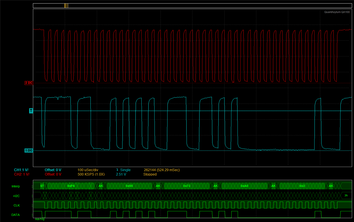
    If I drop the number of masters down to 6 masters instead of 7, the problem goes away. For some reason the i2c bus can handle 6 masters, but when you add the 7th one it starts going haywire. By haywire I mean that if the master fails to communicate, it holds the clock low for a while. Sometimes it holds the clock indefinitely. We have firmware so that if the clock is being held low it'll re-initialize the master i2c. When that was working it still didn't fix the problem. The clk would get released and the master would try again, but it would just NACK and repeat. I show a snip-it of the the NACK and then holding the clk low.

    I do have a question of the buffer chip used in my schematic (TCA9509DGKR). In the launchpad environment, it seems to be hooked up a little bit different. When we hooked up the buffer chip in a different direction from A to B and then from B to A or vise versa, we do get different results. My question is if this chip has shown failures in the past if you hook up this buffer chip differently?

    I hope this makes sense, sorry if it is confusing.

    Best Regards,

    -Thomas Pinewski

  • Hey Thomas,

    The images do not seem to have attached properly, can you please try again? You may want to try consulting the I2C Forum for TCA9509-specific questions, they may also have some advice concerning your multi-master setup. I assume that the UCMM bit is set and each master's own address is programmed into the UCBxI2COA register (as referred to in Section 17.3.4.2 of the User's Guide) and slower than BRCLK/8 bit clock frequencies are used (17.3.5).

    Regards,
    Ryan
  • Do you have contact information for someone I can talk to specifically about the TCA9509 chip? This is kind of an urgent matter.
  • Hello Thomas,
    Please upload your schematic and waveforms. I support TCA9509 (I2C) parts.
    -Francis Houde
  • Hey Francis,

    Here is the schematic for the Master; I just have 1K pull-up on the A side of the buffer chip. Master talks in the direction of A to B. Also attached is my waveform for a successful communication. An unsuccessful communication just shows it trying to send the first byte, then it shows a NACK, then the SCL gets held low.

    I'm wondering if having the buffer chip hooked up like this has caused problem for others? Does it matter which direction the data gets sent? Does it matter which side I have the pull-ups on? Does it matter that I'm only using 1K's?

    Best Regards,

    -Thomas Pinewski

  • Hey Francis,

    Just following up to see if you have looked into my problem at all...

    Best Regards,

    -Thomas Pinewski

  • Hey Thomas,

    Have you considered using weaker pull-ups (try 10 kOhm) and placing them on the slave side?

    Regards,
    Ryan
  • Ryan and Francis,

    When I remove the buffer chip, the boards work well. I've got 9 masters on the bus all communicating. Is it common to have problems with these buffer chips?

    I added the buffer chip to the design to take precautionary measures, because I thought the bus capacitance was going to play a bigger role. At master #9, I'm sure we are over the recommended 400pF capacitance (probably in the 550pF range), but it doesn't seem to make a difference. I'm running the I2C at 50kHz, because it is pretty low data rate. My rise time from 30% to 70% is about 1.2us and my fall time is about 800ns. These rise and fall times seem to be slow compared to what I'm seeing on the web. The data sheets for my microchip and buffer chip don't specify timing requirements for the SDA and SCL rise and fall times.

    Are these rise and fall times typical for the microprocessor I'm using? I recorded these values when there was no buffer chip present. This is purely microprocessor to microprocessor.

    Best Regards,

    -Thomas Pinewski

  • Hi Thomas,

    (Chiming in for Francis here since he is out of the office.)

    Would it be possible to see the waveforms when you have communication issues?

    What might be going wrong with multiple masters connected is you'll have several pull-up resistances connected in parallel. This means the open-drain driver used to pull the I2C signals down (for LOW periods) needs to sink more current. The driver on the A side of TCA9509 is intended to be relatively weak (~200 Ohms), though, and with such a strong pull-up resistance you may not be achieving full logic low levels on the bus. Note that there is already an internal pull-up current on the "A" side of the TCA9509, so no external resistance is needed.

    If this is the root cause of the problem, then Ryan's suggestion to use pull-ups on the B side instead should resolve it.

    Max
  • Unfortunately, I removed the buffer chips from the boards and do not have the failed communication anymore. If I decide to solder new buffer chips on, then I will try and record the failed communication. I think you're right about the pull-up resistors though. When I tested it with a bunch of launchpads, it worked when the pull-up resistors were on the other side of the buffer chip. It still doesn't make complete sense though, because when they're daisy chained together the pull-up resistance will be on both sides...

    Moving forward, I'm needing to decide if a buffer chip is necessary for my applications. Seeing that it works without a buffer chip, are there concerns that I am not taking into account? When I pushed my sampling rate up, I got a fall time of about 200ns, but the rise time is still at 1200ns. Being that I'm running the I2C at a slow 50kHz frequency, is this rise time good enough? I saw that the 1000ns specification is for Standard mode 100kHz frequency...

    Is the buffer chip necessary?
    Does the buffer chip help with anything else besides capacitance and signal integrity?
    Does the buffer chip help with ESD protection?

    Thank you for your help,
    Best Regards,
    -Thomas
  • Thomas,

    If you are able to achieve rise times within spec (you are correct on the 1000 ns upper limit for standard operation) even with worst-case capacitive loading and maximum pull-up resistance, are able to meet input low-level signal thresholds with the minimum pull-up resistance, and do not need logic level translation, then I don't see much of a need for a buffer. I'd say just make sure you are keeping in mind all the different loading conditions (different numbers of masters/slaves along with different PCB trace/cable lengths), have enough margin to account for potential unit-to-unit variation (e.g., on the pull-down strength of the I2C drivers), and make sure that the signals are actually meeting published input high-level and low-level thresholds for all of the I2C devices on the bus.

    Best regards,
    Max
  • Max,

    I do want to use the buffer chips, because I am unsure on a the amount of masters that will be involved in the system eventually.

    I added the buffer chips back onto the boards, and I reworked the boards, so that the 1K pull-up resistors are on the B Side of the chip (according to Ryan's suggestion). The system works with 5 masters, but when I add the 6th master, it fails to communicate.  I captured my wave forms to show you how it is performing. In the first image it shows 2 masters communicating successfully, but then when the 3rd master tries to communicate, it just NACK's off into infinity. 2nd Image shows the NACK zoomed in.

    The buffer chips say that they separate the capacitance on the A side and the B side. Does it do the same with the resistance? As I add masters, are the resistors being added in parallel?

  • Thomas,

    Yes, the resistances would be isolated between the A and B sides. If you had multiple pull-ups on the A side they would combine in parallel, though, and likewise for the B side. Just to double-check - did you remove the pull-ups from the A side as well? If not that could be elevating the low-level voltage, which needs to be 0.3-V or less on the A side in order to properly register as a logic low.

    Sorry to make you jump through a lot of hoops here, but would it be possible to take a look at the waveforms on both the A and B sides of the buffer simultaneously? I'm trying to determine if the signals are not making their way properly between the A and B sides or if the loading of the buffer itself (e.g., the internal pull-up current) is interfering with the masters you are using.

    Also, just to make sure I understand - are you connecting all masters in parallel to the "A" side of a single TCA9509, and all slaves to the "B" side of the same TCA9509?

    Max
  • Max,

    Can I call you?
    I am daisy chaining my boards together, so the first master goes through it's own buffer chip (so one buffer chip). then the second master goes through it's own buffer chip + the buffer chip (so two total buffer chips). then the third etc.

    Does stacking these buffer chips cause problems? For example Master #7 has to go through 7 buffer chips...

    Can we get some faster communication?
    Can I give you my personal email and/or phone number?
    I wasn't planning on this being a public thread...
  • Yes, let's have a call. You can reach me at m-robertson at ti dot com. I need to head out right now but we can find some time tomorrow if that works for you.

    Regards,
    Max
  • The problem was fixed when I removed the 1K pull-up resistors on the masters.
    Not sure why the extra resistance between buffers was causing it to fail, but it works now.

    Thanks for your help.
    -Thomas

**Attention** This is a public forum