This thread has been locked.

If you have a related question, please click the "Ask a related question" button in the top right corner. The newly created question will be automatically linked to this question.

MSP430F5308: ADC10 Design

Part Number: MSP430F5308
Other Parts Discussed in Thread: MSP430F5438

We are going to make a board that measures the battery voltage every five seconds.
So we want to turn the LED on when the measured voltage drops below 3.0 volts.
We are going to use LPM4 to minimize battery power consumption.
("LPM4 : Wait" ↔ (5sec) ↔ "Active Mode : Battery Check")

We are using the MSP430 for the first time. So it is the first ADC function.
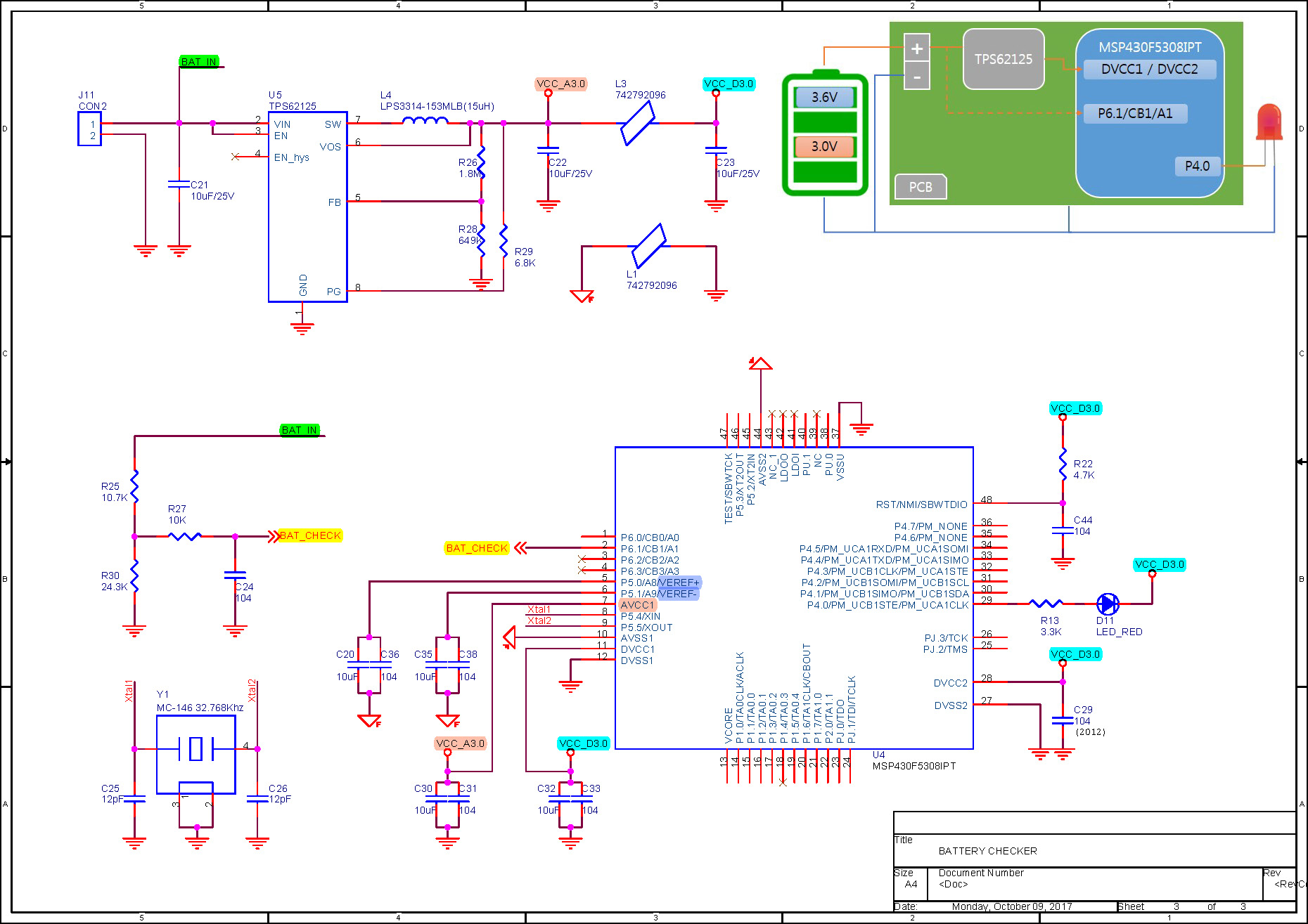
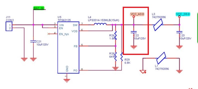
So we designed a circuit with this purpose as follows.The operating environment is as follows.

(1) Vin_max = DC 3.6V
(2) ADC Vref = 2.5 V
(3) Detection voltage: DC 3.0V

We are curious about the following.

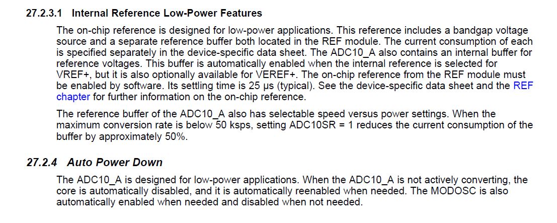
Q1. When using LPM4, what is the advantage of using Vref?      
       External REF. / 2.5V / 2.0V / 1.5V ...?

Q2. If the most advantageous method when using LPM4 is Vref = 2.5V,     
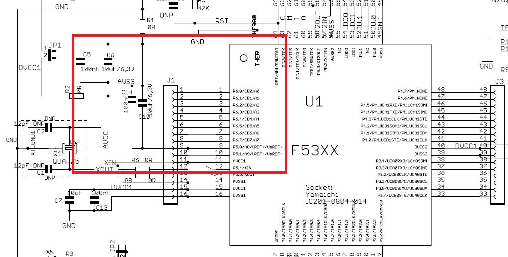
      Can I design the MCU peripheral circuits (VEREF +, VEREF-, AVCC1, AVSS1) as above?

Q3. We selected the R25 and R30 to be 2.5V (ADC Vref) when Vin_max = 3.6V.
       Is this the right way?

  • Hi kang,

    Thank you for posting your question on E2E.

    A1. The internal reference generator of MSP430F5308 is designed for low-power applicationa. So,  There are advantage of low-power feature using the internal reference instead of external. The different selection of reference voltage(1.5V, 2.0V, 2.5V) is based on your input voltage range. According your battery voltage, the 2.5V is appropriate.

    And, the reference generator module of MSP430F5438 have other features as below picture:

    A2. If you use a internal reference, the circuit is OK.

    A3: Yes, The selection of the R25 and R30 to make the max input doesn't exceed the reference voltage is right. And to provide a good resolution, max input should not be too lower than reference voltage. Meanwhile, you should use more accurate resistors to guarantee the measurement precision.

  • Dear Winter,

    Thank you very much for your feedback.
    I am more confident about design than we have before we ask.

    One more question.

    When we tried to use internal reference voltage(2.5V).
    Is the 5(VEREF+),6(VEREF-),7(AVCC1),10(AVSS1) pin connection of "MSP430F5308IPT" correct in the circuit attached to the first inquiry?

    Can I get one more technical support?


    Regards,

    byung chur.

  • Hi byung,

    The connections is no problem. It needs a 10uF and 0.1uF capacitor for de-coupling. You can refer to the schematic and layout of MSP-TS430RGC64B Development Board  .

    It seems that you use magnetic bead to isolate the analog ground and the digital ground. But the VCC_A3.0 needs to connect to the analog ground.

    Regards,

    Winter

    MSP Customer Applications

**Attention** This is a public forum