This thread has been locked.

If you have a related question, please click the "Ask a related question" button in the top right corner. The newly created question will be automatically linked to this question.

MSP430FR2633: Questions about the parasitic capacitance of mutual

Part Number: MSP430FR2633
Other Parts Discussed in Thread: TIDA-00343

Hello,

I have a question.

In the chapter on Common Layout Considerations of CapTIvate technology guide, the following statement was mentioned.

To make sure that the capacitance induced by a finger is large relative to the parasitic capacitance, the total parasitic capacitance (C_parasitics, C_trace, and C_electrode) should be in the range of 10 pF to 20 pF (the change is at least a 5% change). 

According to this description, since two electrodes are required for TX and RX with each other, we think that the parasitic capacitance should be 20 to 40 pF, but is my understanding correct?

Regards,

  • Hello uchida-k,

    C_parasitics refers to the parasitic capacitance of the MCU pin and will not increase per TX/RX line. The C_electrode estimate assumes a filled electrode acting in self-capacitance mode, mutual capacitance electrodes are much less dense and therefore involve less capacitance. Nevertheless, you will need to make sure to keep traces as short as possible, avoid closely routing TX and RX lines and place a ground trace in between (separated by 1/2 panel thickness) if necessary. Be sure to follow all common layout considerations and guidelines for the best mutual design possible.

    Regards,
    Ryan
  • Hi Ryan,

    Thank you for your reply.

    I have additional 5 questions.

    1.In self capacity system, why should the total parasitic capacitance be 10 to 20 pF?

       If C_touch is 1pF, it is because if the change amount is required to be at least 5%, we believe that any value as low as 20pF is acceptable.

       Why do I need parasitic capacitance 10 pF or more?

    2.In the mutual capacitance method, what value range should the parasitic capacitance be?

       Although the parasitic capacitance of the self capacitance method is stipulated as 10 to 20 pF, we do not know how many mutual

       capacities should be done.

    3.What is the intention of "25% fill hatch" in the Pour chapter to make it 25%?

       What is the pitch of the GND line and how wide is it?

    4.About the LEDs / LED Backlighting chapter, what kind of problems are assumed if LEDs are placed at the center of mutual capacity

      type button electrodes on the front side, not on the back side of the board?

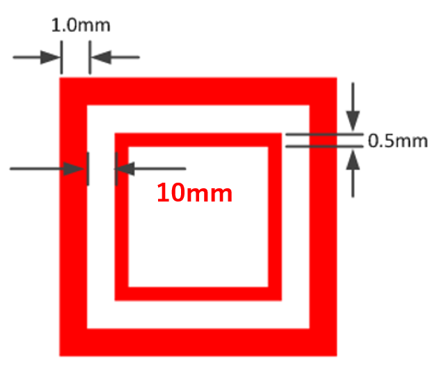
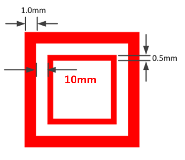
    5.If I want to achieve the touch button of the mutual capacitance method with an overlay of 20mm, if the distance between the TX and

      RX of the electrode as shown in the figure below to 10mm, is it possible sensing?

    Regards,

    uchida-k

  • Hi uchida-k,

    1. You want as little parasitic capacitance in your electrode design as possible, it's great if you can design with less than 10 pF.
    2. Once again, as little as possible is ideal.
    3. Less ground equals less parasitics from traces and electrodes which gives greater sensitivity. 8 mil trace widths with a 24 mil grid size would achieve this but the Development Kit boards go further with 48 and 64 mil grid sizes.
    4. A front-side LED would interfere with the overlay placed on top of the electrodes. A flat PCB is ideal for user interaction.
    5. This would result in a very large button which is not ideal for capacitance, noise susceptibility, or sensitivity. You've already seen the recommended 1/1/0.5 mm and a Dev Kit example uses 1.27/1.27/1.27 mm. Given a thick 20 mm overlay it is highly doubtful that you will sense any capacitive interaction from this design.

    Regards,
    Ryan
  • Hi Ryan,

    thank you for your reply.

    In the mutual capacity method, we think that you can touch with a thicker overlay the further away from the distance between TX and RX. Is my understanding correct?
    What is the trade-off with this?

     A front-side LED would interfere with the overlay placed on top of the electrodes. A flat PCB is ideal for user interaction.

    ->The advantage of placing the LED on the back side is that only PCB becomes flat surfaces?
        Would you tell me if there is another disadvantage of placing the LED on the front?

    Given a thick 20 mm overlay it is highly doubtful that you will sense any capacitive interaction from this design.

    ->What layout is preferable to use the mutual capacity method with a 20 mm overlay?
       How should I fix it from the attached layout earlier?

    Sorry for the many questions.

    Regards,

  • Hello uchida-k,

    If the Rx and Tx electrodes are too close together on a design with a thick overlay, very little field will be penetrating up to the top of the overlay. But if too far apart then they will not be able to couple properly thus creating an ineffective sensor. Self capacitance is the best method for sensing over elongated distances.

    I am not aware of any other disadvantages of front-facing LEDs. There has been no attached layout but once more you should not expect a successful mutual capacitive solution with a 20 mm overlay, just look at Figure 5 in Design Guide -> Best Practices -> Mechanicals -> Overlay.

    Regards,
    Ryan
  • Hi Ryan,

    Thank you for your reply.

    If the Rx and Tx electrodes are too close together on a design with a thick overlay, very little field will be penetrating up to the top of the overlay. But if too far apart then they will not be able to couple properly thus creating an ineffective sensor. Self capacitance is the best method for sensing over elongated distances.


    -> The distance between Tx and Rx was described in the Captivate technology guide as it must be half the thickness of the overlay.
        in case of the mutual capacitance method, how many mm can I increase the distance between Tx and Rx?
        Or, how many mm can the overlay thickness be used up to?

    I am not aware of any other disadvantages of front-facing LEDs. There has been no attached layout but once more you should not expect a successful mutual capacitive solution with a 20 mm overlay, just look at Figure 5 in Design Guide -> Best Practices -> Mechanicals -> Overlay.

    ->In my application, I would like to create a touch button that uses 20 mm overlay and does not malfunction due to moisture.
        Is it possible to realize with the layout below? If the answer is no, how can we change the electrodes of TX and RX?
        Or is it impossible to touch a mutual capacitance system with 20 mm overlay?

    Regards,

  • I only know of proximity applications which can detect beyond 10 mm and this is with poor resolution, as is typical for a proximity sensor. Mutual capacitive button electrode designs require an overlay of less than 4 mm. Please refer to TIDA-00343 which can detect capacitive interaction with up to a 12 mm thick glass overlay, however this is with a self-capacitive design where the buttons are spaced far apart from one another due to the low resolution.

    Regards,
    Ryan
  • Hi Ryan,

    Thank you for your reply.

      Mutual capacitive button electrode designs require an overlay of less than 4 mm. 


    ->What is the material of the overlay mentioned?  Or is it correct with the understanding that the thickness of overlay of mutual capacity method is limited to 4 mm regardless of material (including air gap)?

    I want to avoid false detection due to raindrops of water.

    if you have a good solution to realize a touch sensor with an overlay of 20 mm in an outdoor environment where there is a possibility of rain, please let me know.

    Regards,

  • Hello,

    Is there any update about the above question?

    Regards,

**Attention** This is a public forum