Hello,
I am reviewing a design wherein I've noticed a discrete 0.1uF capacitor has been added to a general purpose output of the MSP to mitigate a system level ESD problem. Not knowing the implementation details of the MSP430 IOBs, had I designed this myself from the start, I would have placed a series resistor ahead of the capacitor to limit the peak drive current to something well within the output capability of the part, say 2mA or so. The GPO is configured for reduced drive strength and it is seldom used. It is a general purpose enable signal that toggles maybe a few times/day. Since I'm late to the party here, and the device is about to enter formal verification phase, I want to know if this could potentially cause a long-term reliability issue with the MSP430, before I report the need to add a current limiting resistor here. I don't want to start any fires on this end unnecessarily.
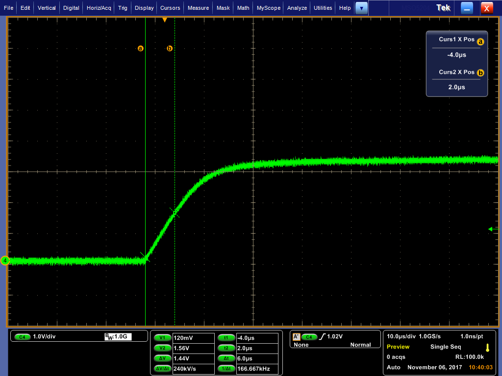
The rising edge of the signal takes about 20us to transition. The worst case slope on the edge occurs within the first 6us or so. From i=Cdv/dt, the current during this time is ~24mA. The scope tracer of the transition is as follows:
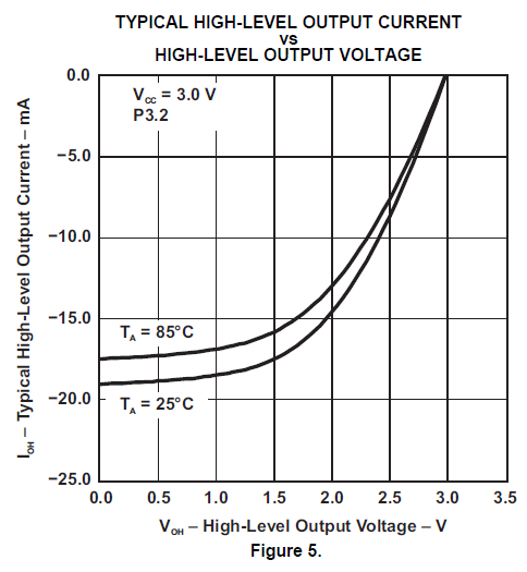
The MSP430 datasheet seems to imply an IOB current limit in the vicinity of 19mA for this scenario, though I'm not sure if this limit is "implemented" or just a limitation of the MOSFET channel.
In any case, I would like to know if TI considers this to be a long-term reliability concern? Could the output driver incur damage over time due to the high instantaneous current?
Thank you,
Chris


