This thread has been locked.

If you have a related question, please click the "Ask a related question" button in the top right corner. The newly created question will be automatically linked to this question.

MSP430F67471A: Questions about VASYS and VDSYS pin

Part Number: MSP430F67471A
Other Parts Discussed in Thread: TIDM-AUX-MODULE

Hello.

I have a question.

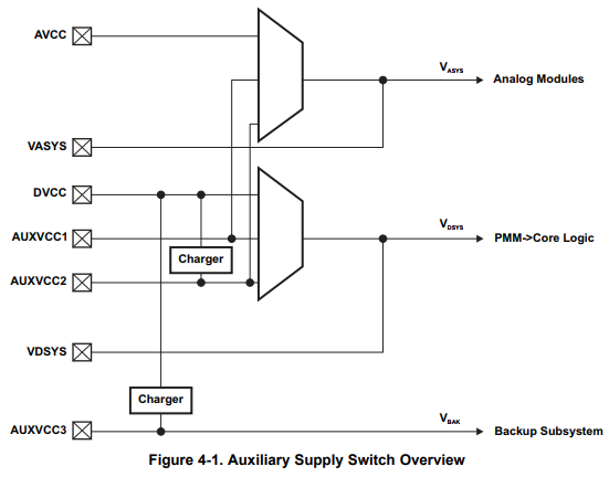
1.Looking at the document 153 page below, the VASYS and VDSYS pins seem to be connected to ground via capacitors of 4.7 uF and 100 nF.

  However currently, on my board, the VASYS and VDSYS pins are pulled down with a 4.7 μA capacitor and are connected to the same supply source of DVCC and AVCC.

  In case of my board connection, what kind of problem are you thinking?

2.The AUXVCC1, AUXVCC2, and AUXVCC3 pins are not used, but they are connected to the same supply source of DVCC and AVCC.
   I am planning to disable AUX VCC by software, but are there concerns such as current consumption going up?

Regards,

  • Hello Keirs,

    Thank you for your post.

    Regarding your first question, I think you're asking if the 100nF capacitors are required. Both the 4.7uF and 100nF capacitors are considered decoupling capacitors where the larger 4.7uF capacitor helps smooth out any voltage drops during high current and the 100nF capacitor helps filter out noise allowing a cleaner supply. According to the datasheet, the 100nF capacitors are not required, but I would recommend them. However, if VASYS or VDSYS are not supplying any other components that are super sensitive to noise, then you shouldn't have any issues.

    For your second question, the NOTE in Section 4.1 in the User's Guide mentions that if AUXVCC1 or AUXVCC2 are unused, they must be connected to DVSS and disabled by setting AUXxMD = 1 and AUXxOK = 0 in software too (which you seem to be planning to do). For AUXVCC3, you can connect it to DVCC externally or internally enable the AUXVCC3 charger. Please refer to the datasheet regarding the recommended capacitors for each AUXVCCx supply. For more details about the AUX modules, refer to the TIDM-AUX-MODULE TI Design. It's extremely helpful and features many different configurations.

    Most importantly, please make sure that VASYS1 and VASYS2 are connected together EXTERNALLY!

    Regards,

    James

    MSP Customer Applications

  • Hi James,

    Thank you for your reply.

    Question1:

     I understand about capacitors.

    I want to know if there are any problem due to connect VASYS to VCC supplying to DVCC and AVCC.

    Although not shown in the data sheet, the VASYS, VDSYS pins are pulled down on the evaluation board.
    Is there any problem if connecting VASYS and VDSYS to VCC?

    Question2:

    I understand.

    Thank you.

    Regards,

  • Hello Keirs,

    It seems like you're asking if VASYS can be connected externally to AVCC and if VDSYS can be connected externally to DVCC. Is this correct?

    Assuming so, I would encourage you to read about the Auxiliary Supply Operation in Section 4.2 in the User's Guide.

    How you connect VASYS and VDSYS depends on your Auxiliary Supply switch configuration. I would recommend looking at Figure 4-1 in the User's Guide.

    Regards,

    James

    MSP Customer Applications

  • Hi James,

    Thank you for your reply.

    I'm not going to use AUXVCC1 and AUXVCC2、AUXVCC3.

    Is there any problem with the configuration below?

    Regards,

  • Hello Keirs,

    Thanks for the diagram. First, I would NOT recommend connecting VCC to VASYS and VDSYS externally, since these pins are already supplied internally by AVCC and DVCC respectively and considered to be outputs.

    Now, I understand that you're not planning to use AUXVCC1, AUXVCC2, or AUXVCC3, so according to the NOTE in Section 4.1 in the User's Guide, connect unused AUXVCC1, AUXVCC2, and AUXVCC3 to DVSS. Even if these aren't used, please keep in mind that the AUX module itself is still used. As described in Section 4.2.1 in the User's Guide, the device starts up whenever a supply is connected to DVCC or AUXVCC1 (refer to Figure 4-1). Since AUXVCC1 is not being used, the AUX module would use DVCC to supply the digital and analog system voltages, VDSYS and VASYS. As shown in Figure 4-1, VDSYS supplies the Power Management Module (PMM) which supplies the digital core of the device with power.

    In summary, I would be very concerned about applying VCC externally to VASYS and VDSYS due to the internal AUX switch.

    Does this answer your question?

    Regards,

    James

    MSP Customer Applications

  • Hi James,

    Thank you for your reply.

    In the case of my current connection method of VDSYS and VASYS, what kind of problems can be considered?

    Regards,
  • Hi,

    Do you have any updates about my question?

    Regards,
  • Hello,

    Unfortunately, I don't have specific information about what problems would be encountered if VCC gets applied to the VDSYS and VASYS pins. We test our devices under the recommended operating conditions. According to the User's Guide, these pins are considered to be outputs. Also, I would be concerned that applying a higher voltage (VCC) to the VDSYS and VASYS pins than what's provided internally (since VCC is applied to the AUX switch which has resistance and would most likely be active not passive circuitry) could cause the device to become unstable.

    Regards,

    James

    MSP Customer Applications

**Attention** This is a public forum