This thread has been locked.

If you have a related question, please click the "Ask a related question" button in the top right corner. The newly created question will be automatically linked to this question.

MSP430F2471: Internal I2C with MSP430F24X1

Part Number: MSP430F2471
Other Parts Discussed in Thread: TMP100, MSP430F249,

Hi, I am working with Humidity sensor  HYT271. It is working fine with bit banging using I2C(I have used I/O lines of MSP430) using external pull-ups. But, to work efficiently I want to use internal i2c. The IDE is code composer studio. The code examples are given for i2c but I am confused to start with that.

Can anyone help me out how to use internal i2c exactly? and provide sample code for any sensor.

  • Hello,

    The I2C examples can only be so specific because each I2C implementation is different. Your best resource is to use the User's Guide along with this Serial Communication Application Report to understand how your specific sensor can be integrated with the MSP430 I2C peripheral.

    Best regards,

    Matt Calvo

  • Thank you, Matthew, for your quick reply. I have gone through the datasheet and application examples for MSP430.

    Here is the code I have used for HYT humidity sensor.

    ************************************************************************************************************

    MSP430x24x Demo - USCI_B0 I2C Master to TMP100, Set P1.0 if Temp > 28C
    //
    // Description: I2C interface to TMP100 temperature sensor in 9-bit mode.
    // Timer_A CCR0 interrupt is used to wake up and read the two bytes of
    // the TMP100 temperature register every 62ms. If the temperature is greater
    // than 28C, P1.0 is set, else reset. CPU is operated in LPM0. I2C speed
    // is ~100kHz.
    // ACLK = n/a, MCLK = SMCLK = TACLK = BRCLK = default DCO = ~1.045Mhz
    //
    // /|\ /|\ /|\
    // | TMP100 10k 10k MSP430F249
    // | ------- | | -------------------
    // +--|Vcc SDA|<-|---+->|P3.1/UCB0SDA XIN|-
    // | | | | | |
    // +--|A1,A0 | | | XOUT|-
    // | | | | |
    // +--|Vss SCL|<-+------|P3.2/UCB0SCL P1.0|---> LED
    // \|/ ------- | |

    ***************************************************************************************************************************************************

     Things I have changed for my sensor( SLAVE Address is 0x28) and MSP430F2471

     Pins for MSP430F2471:

    1. Selected port 5 in my configuration

       45 -SCL (PORT 5.1) 

       46 -SDA(PORT 5.2) 

        P5SEL |= 0x06;     

    2. Changed USCI module registers from 0 to 1

        Changed UCB1CTL0 to UCB1CTL1 

    3. Changed UCB0CTL0 to UCB1CTL0

    4. Changed UCB0BR0 to UCB1BR0

    5.  Changed UCB0BR1 to UCB1BR1

    6. UCB0I2CSA to UCB1I2CSA

    7. Set the slave address to 0x28

    8. Changed UCB0RXIE to UCB1RXIE   // Enable Receiver interrupt 

    9. UCB0RXBUF to  UCB1RXBUF

    10.USCIAB0TX_ISR to USCIAB1TX_ISR


    #include <msp430.h>

    unsigned int RxByteCtr;
    unsigned int RxWord;

    int main(void)
    {
    WDTCTL = WDTPW + WDTHOLD; // Stop WDT
    P1OUT = 0;
    P1DIR |= 0x01;                            // P1.0 output
    P5SEL |= 0x06;                           // Assign I2C pins to USCI_B0
    UCB1CTL1 |= UCSWRST; // Enable SW reset
    UCB1CTL0 = UCMST + UCMODE_3 + UCSYNC; // I2C Master, synchronous mode
    UCB1CTL1 = UCSSEL_2 + UCSWRST; // Use SMCLK, keep SW reset
    UCB1BR0 = 12; // fSCL = SMCLK/12 = ~100kHz
    UCB1BR1 = 0;
    UCB1I2CSA = 0x28; // Set slave address
    UCB1CTL1 &= ~UCSWRST; // Clear SW reset, resume operation
    IE2 |= UCB1RXIE; // Enable RX interrupt
    TACTL = TASSEL_2 + MC_2; // SMCLK, contmode

    while (1)
    {
    RxByteCtr = 2; // Load RX byte counter
    UCB1CTL1 |= UCTXSTT; // I2C start condition
    __bis_SR_register(CPUOFF + GIE); // Enter LPM0, enable interrupts
    // Remain in LPM0 until all data
    // is RX'd

    if (RxWord < 0x1d00) // >28C?
    P1OUT &= ~0x01; // No, P1.0 = 0
    else
    P1OUT |= 0x01; // Yes, P1.0 = 1

    __disable_interrupt();
    TACCTL0 |= CCIE; // TACCR0 interrupt enabled
    __bis_SR_register(CPUOFF + GIE); // Enter LPM0, enable interrupts
    // Remain in LPM0 until TACCR0
    // interrupt occurs
    TACCTL0 &= ~CCIE; // TACCR0 interrupt disabled
    }
    }

    #if defined(__TI_COMPILER_VERSION__) || defined(__IAR_SYSTEMS_ICC__)
    #pragma vector = TIMERA0_VECTOR
    __interrupt void TA0_ISR(void)
    #elif defined(__GNUC__)
    void __attribute__ ((interrupt(TIMERA0_VECTOR))) TA0_ISR (void)
    #else
    #error Compiler not supported!
    #endif
    {
    __bic_SR_register_on_exit(CPUOFF); // Exit LPM0
    }

    // The USCIAB0TX_ISR is structured such that it can be used to receive any
    // 2+ number of bytes by pre-loading RxByteCtr with the byte count.
    #if defined(__TI_COMPILER_VERSION__) || defined(__IAR_SYSTEMS_ICC__)
    #pragma vector = USCIAB0TX_VECTOR
    __interrupt void USCIAB1TX_ISR(void)
    #elif defined(__GNUC__)
    void __attribute__ ((interrupt(USCIAB1TX_VECTOR))) USCIAB1TX_ISR (void)
    #else
    #error Compiler not supported!
    #endif
    {
    RxByteCtr--; // Decrement RX byte counter

    if (RxByteCtr)
    {
    RxWord = (unsigned int)UCB0RXBUF << 8; // Get received byte
    if (RxByteCtr == 1) // Only one byte left?
    UCB1CTL1 |= UCTXSTP; // Generate I2C stop condition
    }
    else
    {
    RxWord |= UCB1RXBUF; // Get final received byte,
    // Combine MSB and LSB
    __bic_SR_register_on_exit(CPUOFF); // Exit LPM0
    }
    }

    Things I have noticed while debugging using CRO :

    1. The SCL is not generating any clock.


    Let me know if any modification required in the code for generating clock, start and stop condition.

    Looking for your reply


  • > IE2 |= UCB1RXIE; // Enable RX interrupt
    UCB1RXIE is in UC1IE, not IE2. (Ref SLAU144J Sec 17.4.13) This is only half a theory, since I don't know what (in this program) could cause UCB0RXIFG to trigger. Anyway, you probably want to fix it.
  • I have to read 4 bytes of humidity data. For that I need to generate clock, start and stop which is not happening.
    Is there any wrong in my code for generating these conditions. Let me know the required register configurations,
  • Except for the IE thing, I don't see anything obviously wrong.

    What is the state of SDA/SCL?
  • The state of SDA and SCL is high with power on due to external 3.3K pull-ups. So, What's wrong with IE.

    Can you suggest the right configuration for it?

    First thing I want to do is generate the clock, and start condition and wait for the sensor acknowledgment.

    Afterwards, I will think about reading the sensor data.

  • > IE2 |= UCB1RXIE; // Enable RX interrupt
    should be
    > UC1IE |= UCB1RXIE; // Enable RX interrupt

    Also
    > #pragma vector = USCIAB0TX_VECTOR
    should be
    > #pragma vector = USCIAB1TX_VECTOR

    > RxWord = (unsigned int)UCB0RXBUF << 8; // Get received byte
    should be
    > RxWord = (unsigned int)UCB1RXBUF << 8; // Get received byte

    All of these will cause trouble eventually, but none should prevent activity on SCL/SDA -- at the very least you should get the address byte.

    What does the debugger say? Also, what kind of board is this?
  • Thank you Mr.Bruce for your suggestion.
    I will try this out and get back to you.
  • I had finally got SCL and SDA output from the sensor by going through the datasheet and application report. But still, I have some issues.

    Things I have done to generate clock and data:

    ***************************************************

     UCB1BR0 = 12;                                           // fSCL =SMCLK/12 = ~100kHz

     UCB1BR1 = 0;

     UCB1I2CSA = 0x51;                                  // default  slave address (0x28 )given in the sensor data sheet

     *******Continuous loop for Start,and Stop and Write address of Slave *****************

     while(1)

    {

    UCB1CTL1 |= UCTXSTT;                       // I2C start condition

    UCB1CTL1 |= UCTXSTP;                      // Generate I2C stop condition

    }

    Other than above I have set necessary configurations for USCI module.

    My question as per I2C protocol and data sheet gave the Start sequence, 7-bit slave address, and write bit the calculated byte for the slave write address 0x28 are 0x51.

    So I have set  UCB1I2CSA = 0x51.

    So, after transmitting start, slave write address the acknowledgment has to be given from the sensor in the 9th clock pulse by making the SDA line low which is not happening.

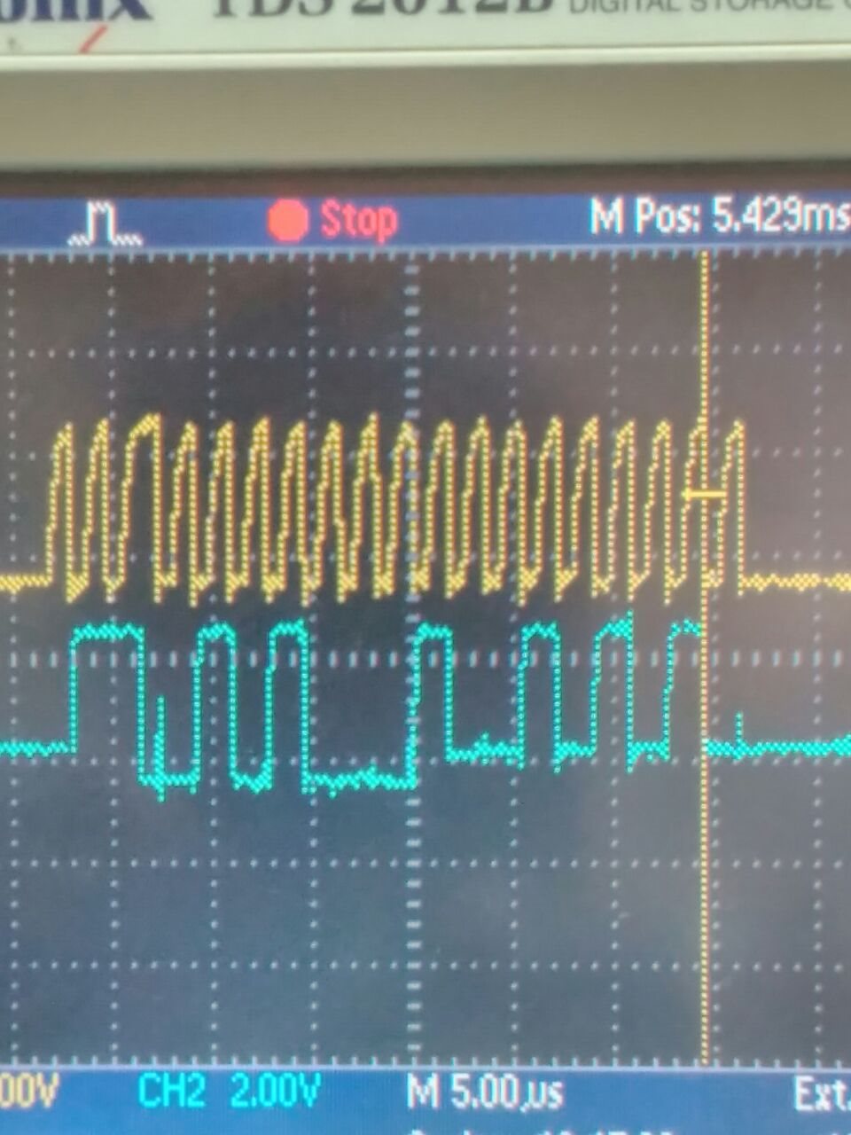
    The clock pulses generated are like spikes. Are they correct? Is there anything required for the clock pulses.

    Can anyone help me to analyze this situation? I have seen this response from the CRO.

  • Swaroop,

    One thing noticed in your code:

    UCB1I2CSA = 0x51; // default slave address (0x28 )given in the sensor data sheet

    It looks like the slave address is 0x28 and not 0x51. You may have chose 0x51 because you thought the 7 bit address needed to be shifted left to make room for the r/w bit but that is not the case. You should be writing the slave address as 0x28 to this register instead.

    As far as the slow rise time for the SCL and SDA lines, this could be a result of multiple things. It could either be a result of the capacitance on the lines being too high or the pull-up resistors being too large. This would effectively increase the RC time constant on the data and clock lines and cause the rise time to be slower. A possible solution for this could be to lower the resistor values on the lines which will make for a stronger pull-up.

    If these possible solutions still don't resolve the issues you are experiencing then it may be time so send your source code so that we could possibly see what the issue is.

    Best regards,

    Matt Calvo
  • Swaroop is casting a wide net: e2e.ti.com/.../653403

    Regards,
    Ryan
  • Swaroop,

    I will keep this thread open just for a placeholder but will continue to keep an eye on your same issue on the other e2e post (https://e2e.ti.com/support/microcontrollers/msp430/f/166/t/653403).

    Best regards,

    Matt Calvo

  • Your clock pulses are like spikes because you have a slow rise time. The rise time is determined by the pull-up resistor. This is because your pull-up resistor isn't pulling the bus up to VDD fast enough (the device yanks down on the lines, which look fine). So you could reduce the resistance. Or doe you have a lot of capacitance on your bus? Also, you could reduce the frequency of you internal clock.
  • Hi to all,

    From the above solutions suggested I have tried with I got something by putting  I2C1SA=0X28 with the following code. Let's have a look.

    The below code is working when these 2 lines are commented.

      change 1.

     //__bis_SR_register(CPUOFF + GIE);  

      change 2.  

    //  __bic_SR_register_on_exit(CPUOFF);      // Exit LPM0    

    I don't know why there are no traces of SCL and SDA when I uncomment above  2 lines.

    I have used this line of code to enable Interrupts.

    Change 3.

    __bis_SR_register(GIE);

    Change 4:

    RXByteCtr=2

    The below is the screenshot on the oscilloscope for the following code.

    //********************************************************************//

    #include "msp430x24x.h"

    #include "stdio.h"

    unsigned char *PRxData;                     // Pointer to RX data

    unsigned char RXByteCtr;

    volatile unsigned char RxBuffer[128];       // Allocate 128 byte of RAM

    int main(void)

    {

      WDTCTL = WDTPW + WDTHOLD;                 // Stop WDT

      BCSCTL1 &= ~XT2OFF;       // Activate XT2 high freq xtal

      BCSCTL2 =0x88;  

     P5SEL |= 0x06;                            // Assign I2C pins to USCI_B0

     UCB1CTL1 |= UCSWRST;                      // Enable SW reset

     UCB1CTL0 = UCMST + UCMODE_3 + UCSYNC;     // I2C Master, synchronous mode

     UCB1CTL1 = UCSSEL_2 + UCSWRST;            // Use SMCLK, keep SW reset

     UCB1BR0 = 12;                             // fSCL = SMCLK/12 = ~100kHz

     UCB1BR1 = 0;

     UCB1I2CSA = 0x28;                         // Slave Address is 0x28

     UCB1CTL1 &= ~UCSWRST;                     // Clear SW reset, resume operation

     UC1IE |= UCB1RXIE;                          // Enable RX interrupt

     __bis_SR_register(GIE);

     while (1)

     {

       PRxData = (unsigned char *)RxBuffer;    // Start of RX buffer

       RXByteCtr = 2;                          // Load RX byte counter

       while (UCB1CTL1 & UCTXSTP);             // Ensure stop condition got sent

       UCB1CTL1 |= UCTXSTT;                    // I2C start condition

     //__bis_SR_register(CPUOFF + GIE);        // Enter LPM0 w/ interrupts

                                               // Remain in LPM0 until all data

                                               // is RX'd

       __no_operation();                       // Set breakpoint >>here<< and

     }                                         // read out the RxBuffer buffer

    }

    //-------------------------------------------------------------------------------

    // The USCI_B0 data ISR is used to move received data from the I2C slave

    // to the MSP430 memory. It is structured such that it can be used to receive

    // any 2+ number of bytes by pre-loading RXByteCtr with the byte count.

    //-------------------------------------------------------------------------------

    #if defined(__TI_COMPILER_VERSION__) || defined(__IAR_SYSTEMS_ICC__)

    #pragma vector = USCIAB1TX_VECTOR

    __interrupt void USCIAB1TX_ISR(void)

    #elif defined(__GNUC__)

    void __attribute__ ((interrupt(USCIAB1TX_VECTOR))) USCIAB1TX_ISR (void)

    #else

    #error Compiler not supported!

    #endif

    {

     RXByteCtr--;                              // Decrement RX byte counter

     if (RXByteCtr)

     {

       *PRxData++ = UCB1RXBUF;                 // Move RX data to address PRxData

       if (RXByteCtr == 1)                     // Only one byte left?

         UCB1CTL1 |= UCTXSTP;                  // Generate I2C stop condition

     }

     else

     {

       *PRxData = UCB1RXBUF;                   // Move final RX data to PRxData

     //  __bic_SR_register_on_exit(CPUOFF);      // Exit LPM0    

     }

    }

    My questions:

    1. What is the value to be loaded into RXByteCtr, How to choose the value and Is my value 2 is correct?

    2. For the above code am I getting the 2 bytes humidity data from the sensor? If not how to read using UCTR bit suggest the code sample for reading using UCTR

    3. How to see the UCB1RXBUF data in debug mode I am not able to see any value in the register when I set the breakpoint. I have not mentioned any uart code in above code.

        But I have sent UCB1RXBUF using the uart on to hyper terminal, hex values observed are some 00 and 8.

    Help me to solve this.

    Regards,

    Swaroop.


  • Swaroop,

    As I mentioned above, please post and allow us to support on this issue on your newest e2e thread ( https://e2e.ti.com/support/microcontrollers/msp430/f/166/t/653403  ) since it is further along in its progression than this thread. Both Ryan and I will be able to assist you there. It will be easiest to track and follow to a resolution if the communication is focused to a single thread so please copy your previous post to the new thread so we can keep supporting your issue.

    Best regards,

    Matt Calvo

  • Matt is correct that you need to stop jumping between discussions.

    1) 2 is the correct RXByteCtr value to retrieve humidity (only -- no temperature).
    2) Since you haven't set it, UCTR=0, so you're doing a read (a Data Fetch). To do a write, set UCTR=1 before/during issuing the UCTXSTT. You'll need to put some transmit code into the ISR.
    3) I expect the first byte you read to have the 0x40 bit ("stale") set, since you haven't done a Measurement Request. (As near as I can tell, MR is just a Write with no data.) AHHYTM_E doesn't say what the other bits in a "stale" reading look like. What data did you get when you were bit-banging the I2C?

    That trace looks like a fragment: (1) it starts and ends low (2) it has 19 clocks, which is either too few or too many. If I squint, I can kind of see the address byte 0x51+ack, then 0x5_ , which has the "stale" bit but is truncated.

    What does your debugger say? Try setting a breakpoint on the second statement in main (the debugger may mess with the first statement) and see if you turn up there unexpectedly.

    Also, you really should be waiting for the transaction to complete before issuing another UCTXSTT. If CPUOFF isn't working for you (I don't know what that might be) try just spinning until RXByteCtr == 0, at which point UCTXSTP should be set.
  • Dear Bruce and Matt,
    Thank you for the support till now. I have done all the things mentioned. As from the previous discussions,
    I have set I2C1SA=0X28, but do I need to send the write and read address to the humidity sensor other than the nomial address.

    Please clarify. Waiting for your reply.

    Regrads,
    Swaroop.
  • > What data did you get when you were bit-banging the I2C?
    > What does your debugger say?

    I don't have your equipment, and your observations are very much at odds with my experience with the F2 I2C (both native and bit-banged). Without clues I'm just guessing.

    I more and more suspect something electrical: (a) the SCL traces are "ratty" compared with the SDA traces (b) your scope fragments suggest random (perhaps even data-dependent) MCU resets.
  • Swaroop,

    Have you had a chance to consider responding to Bruce? We hope to help you find a solution to this I2C problem you've been experiencing.

    Best regards,

    Matt Calvo

  • Swaroop,

    It has been a little while since we have heard from you. Are there any outstanding issues? If not I am going to close this thread out and log it for tracking purposes. Thank you for your support!

    Best regards,

    Matt Calvo
  • Swaroop,

    Since support for this thread seems to be complete I am going to go ahead and close this thread out. Should you run into additional issues please feel free to make another E2E post to address your problem.

    Best regards,

    Matt Calvo

**Attention** This is a public forum