This thread has been locked.

If you have a related question, please click the "Ask a related question" button in the top right corner. The newly created question will be automatically linked to this question.

MSP430F5325: MSP430F5x Flash based custom UART boot loader

Part Number: MSP430F5325
Other Parts Discussed in Thread: MSP-FET

Hi,

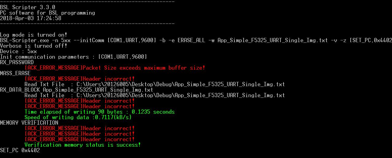
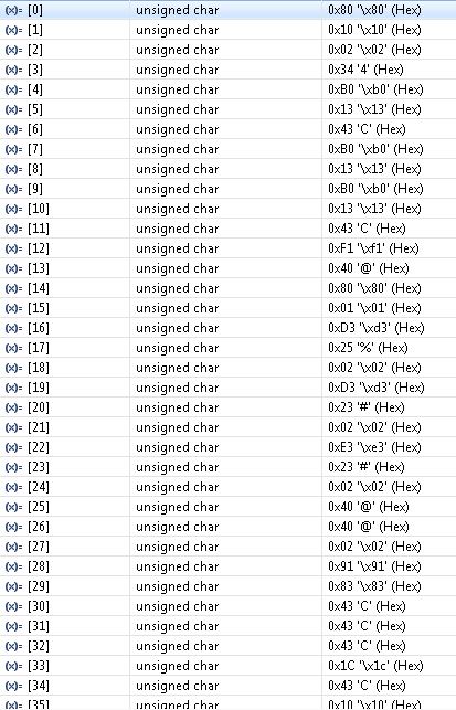
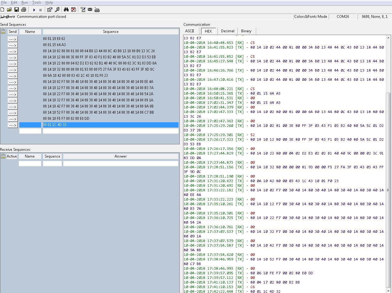
We are planning to create a UART based custom boot loader for MSP430F5325. We cannot use any JTAG lines, we can only use its UART TX and RX pins P3.3 and P3.4. So we are planning to create a custom flash based boot loader which takes bin image from UART and load in to the application area.

Basically we are planning to create a code with UART to take date and flash it into the application area. This will acting as boot loader code and after updating it will jump into the application area.

The linker file of the BL will be only in FLASH location : origin = 0x4400, length = 0xBB80 and our application code linker file will be only in FLASH2 : origin = 0x10000,length = 0x4400.

We have seen some BSL scripter and custom BSL examples, so please let us know how we can use those in our application and it seems like it is using some pins in JTAG which we cant use in our application. So please let us know your thoughts on the above method and let us know if there is any risks.

Thanks

Rahul

  • Hello,

    You have a few options here. The MSP430F5325 already has a UART based BSL (Timer Based UART implementation). It uses pins P1.1 and P1.2 for this. In order to sue the BSL, it must be invoked. the typical way of doing this is with an entry sequence on the Test and RST pins. You can also enter the BSL via a SW  Entry from your application. You could then program your application to invoke the BSL  with a sequence of GPIO switching or a certain data stream on the UART. There are a few other options as well I'll outline below. That being said there are several methods that allow you to use the BSL are w/o having to half your application space.

    1. Use UART BSL currently on chip, and invoke via SW entry. Trigger the SW entry with some criteria in your application (UART Stream, GIPO Toggle, etc)
    2. Customize the BSL to use the UART module (P3.3 and P3.4) and do the same SW entry described in point 1.
    3. Modify MSPBOOT to do everything form the application side of Flash.
    4. Customize the BSL to use UART module, and modify the entry sequence to a custom one (change BSL Invoke Function).

    I've laid out the options in order of ease to implement with option 1 being the easiest to implement and option 4 being the hardest to do. Option 3 will take up the most resources however, and option one maybe tricky if you are trying to use the same UART lines for BSL and application. Option 2 is probably your best bet and the cleanest solution.

  • Hi,

    Thanks for your immediate and valuable response response. Please let me know your comments on the following also,

    1. So in case of option 2, can we use same BSL scripter windows application to send image file from pc?
    2. Also can we use simple TTL to USB converter to convert the MSP430 UART to USB and connect that to PC?
    3. In option 2, it will be really helpful if you could let us know if there any doc or code to customize the BSL and updating the existing with the customized one?

    Thanks
    Rahul

  • Rahul,

    To use the BSLScripter, you will need the Test and RST connections in order to invoke the BSL.  If these pins a are not available, then you cannot use the BSLScripter. If you only change the peripheral interface BSL and its a supported interface (UART/I2C), the the BSLScripter will still work in that regard, but other customization will not work (aka changing invoke sequence).

    Using a TTL converter has been done before by customers. I see no issue with this providing you have a way of doing the entry sequence on TEST and RST. I believe  customers have had success in doing this with the flow control lines.

    All custom BSL documentation and code can be found at . Here you will find the Creating a Custom BSL app note as well as its associated SW package CUSTOM-BSL430.

  • Hello,

    Thanks for the response and we will check that links.

    But our problem here is we can use TEST and RST pin or JTAG for our initial loading for bootloader but once it is shipped to customer he cannot use JTAG or TEST and RST pin, it is not available for them. They can only use the pins P3.3 and P3.4 and connect that to PC. With only those pins customer need to update his firmware. So customer cannot invoke any sequence using TEST and RST pin or JTAG. So can we customize the BSL to change the entry sequence from TEST and RST pins to some button combination? So while booting if that button is pressed it will go to BSl and wait for the image file from PC and it will load to application area and jumps to application area. Please let me your thoughts on this.

    Also if we cannot use BSLScripter i assume we need to create a windows application also to send our image file to MSP via com port. Is that correct? Or please let us know if there is any other solution to send image file from PC to MSP via com port?

    Thanks
    Rahul

  • Rahul,

    Yes, you can change the BSL Invoke method to whatever you want. In fact on our USB Devices, which have a USB based BSL, it looks for the PUR pin being high right after startup in order to boot into BSL mode.

    I did just get confirmation that the BSLScripter doesn't really have a way to know if the part is in BSL mode (therefore it doesn't check). This means if you ahve an alternate way of invoking the BSL, if you make sure the part is in BSL mode before sending commands via the BSLScripter, you should be able to use it. Provided you are suing a standard peripheral interface it supports (aka UART or I2C).
  • Hello Jace,

    Thanks, That sounds great. So basically if we change the BSL invoke method to our custom one then we can use the same windows BSL scripter to update the firmware via UART using only P3.3 and P3.4 pins of MSP430F5325.

    As per our understanding here are the steps, please correct us if we are wrong or missing any steps,

    1. we need to change the MSPBoot_UART_F5529 code for MSP430F5325 and its .cmd file for correct memory locations.
    2. This code will 1st check if the Boot is forced or not, so customize boot forcing section as per our need.
    3. If boot is forced, it will initialize UART pins so change as per our needs and then it check for data from UART. Load this code to MSP430F5325 using JTAG.
    4. Then initiate the custom boot sequence and connect the device to PC using UART pins P3.3 and P3.4 . Using windows BSL Scripter application load the application code.
    5. Then  BSL will then jump to application area.

    Please let us know if our understanding is correct or if we are missing any steps.

    Thanks
    Rahul

  • Rahul,

    Either the BSL Security or BSL Invoke check function is the first thing called upon startup of a device (check documentation for exact sequence). So if you just change the mechanism of how this function knows to boot in BSL mode, you don't have to write any of the checks you are talking about. You would then just swap out the Peripheral Interface code to use the HW UART, the the BSL will just work like normal, albeit with a different invoke method and HW UART interface. How to do this is listed in the Custom BSL document and its references.
  • Hi Jace,

    We created a MSPBoot UART single image code and its application code and tried with windows BSL Scripter application, but it seems like BSL Scripter generates 9601 baud rate to invoke the pin sequence to activate the BSL on the MSP-FET and Rocket hardware. This cannot be done in our case since it is using only TX and RX lines and also the COM port which we are using is COM1 which may not be capable of custom baud rates. In this case it was showing errors in setting up the com port, So we changed the the following in UartComm.h file

    static const uint32_t INVOKE_430_BSL_ADD = 1;

    to

    static const uint32_t INVOKE_430_BSL_ADD = 0;

    Now we can see the windows application running but it is showing some header errors and not updating the firmware,

    Please let us know where we are going wrong.

    Thanks

    Rahul

  • Rahul,

    The "9601" Baud rate is just a code for the translate HW (aka Rocket or MSP-FET) to do the invoke sequence. The UART will still be set to 9600 Baud when the actual communication is done. What does your script look like?

  • Hi Jace,

    As you can see in image of my above post, we are using command line,

    BSL-Scripter.exe -n 5xx --initComm [COM1,UART,9600] -b -e ERASE_ALL -w App_Simple_F5325_UART_Single_Img.txt -v -z [SET_PC,0x4402]

    Regarding the "9601" Baud rate, if we are not changing the value as i mentioned in my previous post its is showing error in setting the serial communication and after changing only it started working.

    On further debugging, we found that the MSP430 is receiving 0x80 0x21 0x00 0x11 data from PC application via UART, in which 0x80 can be header and the next byte it is checking for length. But it seems like the max length as per the code is

    /*! Maximum size of data payload = 16 data + 1 CMD + 3 ADDR */
    #define PAYLOAD_MAX_SIZE (16+1+3)

    and we are getting 0x21 from PC application. May be this is why we are getting

    [ACK_ERROR_MESSAGE]Packet Size exceeds maximum buffer size!

    error in the starting.

    Please let us know where we are going wrong here.

    Thanks
    Rahul
  • Rahul,

    Command Line only is hard to debug and not the easiest to replicate to multiple units. Use a script so you can control the exact transactions you want to do. It also allows you to control timing better for loading images. Please see the script examples within the Custom BSL SW download.
  • This may not be relevant, but be sure the PC COM port is being set to even parity if you are using a USB-to-UART adapter.

  • Hi Jace,

    We will try that and let you know the updates.

    Thanks

    Rahul

  • Hello George,

    We assume if parity is wrong then all bytes will be wrong. But we are seeing 0x80 as 1st byte which we think that it will be header. Is our understanding correct? Anyway we will try changing parity also and it will be really helpful if you could let us know how can we change that in the bsl scripter application.

    Thanks
    Rahul
  • I don't think the 0x80 tells you that parity is set correctly.  0x80 would have an even parity bit of "1" at the end of the byte, but that is the same value as the stop bit.  So that 1 could be the parity bit, or it could be no parity,  but  just a long stop bit, or two stop bits.

    All of my experience is with the G2553 and BSLDEMO, so I'm not able to give you much advice about the F5xx parts and Scripter.  But it is curious to me that after the 0x80 is sent, the next byte is an illegal value.  One possible explanation is that the baud rate at the receiver is being set incorrectly after the 0x80 is received.  The BSL for the G2553 also expects an 0x80, and it uses that to actually calculate the baud rate.  Perhaps your F5325 does the same thing, but the processor clock is wrong, or some other error is changing the baud rate.  If you stretch out the 0x21 (00100001), it could be a 0x2 (P00000010) or 0x4 (P00000100) with an even parity bit.  

    Well, I'm just guessing.  But it would be interesting if you could capture what Scripter is sending on your scope or logic analyzer and see what it actually is.  I don't think the F5325 would even need to be connected to do that test.  Scripter probably sends the initial packet at 9600 baud without knowing if anything is listening.

    I don't know if you can change parity within Scripter.  It probably uses whatever the Rocket or MSP-FET expects.  But you should be able to bring up the COM port in Device Manager and set the parity there.

    Edit:  It looks like I was wrong about changing parity within Scripter.  It appears there is a PARITY option in the MODE command that sets even parity.  Without that, it defaults to no parity.  But that's if you use a script.  I don't see a way to set even parity from the command line.  "--initComm" doesn't seem to have that option.

    Edit2:  I tried something similar to what  you were doing, but with no MSP part connected, and got the following verbose log file:

    ---------------------------------------------------------
    BSL Scripter 3.3.0
    PC software for BSL programming
    2018-Apr-04 18:52:54
    ---------------------------------------------------------
    bsl-scripter -i [COM4,UART,9600] -d -n 5xx -b -e ERASE_ALL
    Verbose is turned on!
    Device : 5xx
    Init communication parameters : [COM4,UART,9600]
    RX_PASSWORD
     [80] [21] [00] [11] [ff] [ff] [ff] [ff] [ff] [ff] [ff] [ff] [ff] [ff] [ff] [ff]
     [ff] [ff] [ff] [ff] [ff] [ff] [ff] [ff] [ff] [ff] [ff] [ff] [ff] [ff] [ff] [ff]
     [ff] [ff] [ff] [ff] [9e] [e6]
     [ACK_ERROR_MESSAGE]Unknown ACK value!
    MASS_ERASE
     [80] [01] [00] [15] [64] [a3]
     [ACK_ERROR_MESSAGE]Unknown ACK value!

    So the length byte could be correct for a 32-byte password.  But what I see on the scope looks different from that.  The 0x80 looks the same, but after that it looks different.  I'll see if I can figure it out.

    Edit 3:  Ok, what I was seeing on the scope was the second MASS-ERASE command, and the six bytes in the log are exactly what is sent.  But it's no parity.  See the following post.

  • From my scope capture, it looks like everything is being transmitted correctly, except that it's definitely no parity. I tried going into Device Manager and setting the COM port paramters to even parity, but Scripter transmits no parity anyway. I don't think there is a way to make it send even parity from the command line entry.

    But if you change your input to a script file, and add "PARITY" to the MODE line, it will transmit in even parity. I strongly suspect that's what your problem is. BSL is expecting even parity, but getting no parity, so after the 0x80, the bytes may be interpreted incorrectly.
  • Hi George,

     Thats great, we really appreciate your time and effort. whatever data you have mentioned 

    George Hug said:

    Init communication parameters : [COM4,UART,9600]
    RX_PASSWORD
     [80] [21] [00] [11] [ff] [ff] [ff] [ff] [ff] [ff] [ff] [ff] [ff] [ff] [ff] [ff]
     [ff] [ff] [ff] [ff] [ff] [ff] [ff] [ff] [ff] [ff] [ff] [ff] [ff] [ff] [ff] [ff]
     [ff] [ff] [ff] [ff] [9e] [e6]
     [ACK_ERROR_MESSAGE]Unknown ACK value!
    MASS_ERASE
     [80] [01] [00] [15] [64] [a3]
     [ACK_ERROR_MESSAGE]Unknown ACK value!

    is exactly what we we seeing here. We tried with script file and changing the parity, but still we are facing some issues. Now we can see the data like this,

    and the output like this

    ---------------------------------------------------------
    BSL Scripter 3.3.0
    PC software for BSL programming
    2018-Apr-06 11:01:28
    ---------------------------------------------------------
    Input file script is : C:/Users/20126005/Desktop/Debug/script_5xx_uart.txt
    MODE 5xx UART COM1 9600 PARITY
    //gives the wrong password to do
    //mass eraseof the memory
    RX_PASSWORD .\pass32_default.txt
    Read Txt File : C:\Users\20126005\Desktop\Debug\pass32_default.txt
    RX_DATA_BLOCK .\blinkLED_f5325.txt
    Read Txt File : C:\Users\20126005\Desktop\Debug\blinkLED_f5325.txt
    [ACK_ERROR_MESSAGE]Checksum incorrect!
    [ACK_ERROR_MESSAGE]Header incorrect!
    [ACK_ERROR_MESSAGE]Header incorrect!
    Time elapsed of writing 164 bytes : 0.222 seconds
    Speed of writing data :0.7213(kB/s)
    SET_PC 0x4402

    Please let us know where we are going wrong.

  • Hi Jace,

    we have tried with script file also but still we are facing some issues. Script file is as follows,

    LOG

    MODE 5xx UART COM1 9600 PARITY

    RX_PASSWORD .\pass32_default.txt

    RX_DATA_BLOCK .\blinkLED_f5325.txt

    SET_PC 0x4402

    and the output we are getting is

    ---------------------------------------------------------

    BSL Scripter 3.3.0

    PC software for BSL programming

    2018-Apr-06 11:01:28

    ---------------------------------------------------------

    Input file script is : C:/Users/20126005/Desktop/Debug/script_5xx_uart.txt

    MODE 5xx UART COM1 9600 PARITY

    //gives the wrong password to do

    //mass eraseof the memory

    RX_PASSWORD .\pass32_default.txt

    Read Txt File  : C:\Users\20126005\Desktop\Debug\pass32_default.txt

    RX_DATA_BLOCK .\blinkLED_f5325.txt

    Read Txt File  : C:\Users\20126005\Desktop\Debug\blinkLED_f5325.txt

    [ACK_ERROR_MESSAGE]Checksum incorrect!

    [ACK_ERROR_MESSAGE]Header incorrect!

    [ACK_ERROR_MESSAGE]Header incorrect!

    Time elapsed of writing 164 bytes : 0.222 seconds

    Speed of writing data :0.7213(kB/s)

    SET_PC 0x4402

    please check attached files for more details and let us know your comments.

    Thanks

    Rahul

    blinkLED_f5325.txt
    @4402
    81 00 00 34 B0 13 48 44 0C 43 B0 13 18 44 B0 13 
    42 44 FF 3F 03 43 F1 03 B2 40 80 5A 5C 01 D2 D3 
    25 02 D2 D3 23 02 D2 E3 23 02 B1 40 40 9C 00 00 
    02 3C 91 83 00 00 81 93 00 00 F5 27 FA 3F 03 43 
    03 43 FF 3F 03 43 1C 43 10 01 
    @f702
    30 40 14 44 30 40 14 44 30 40 14 44 30 40 14 44 
    30 40 14 44 30 40 14 44 30 40 14 44 30 40 14 44 
    30 40 14 44 30 40 14 44 30 40 14 44 30 40 14 44 
    30 40 14 44 30 40 14 44 30 40 14 44 30 40 14 44 
    30 40 14 44 30 40 14 44 30 40 14 44 30 40 14 44 
    30 40 14 44 30 40 14 44 
    @f7fe
    02 44 
    q
    
    pass32_wrong.txt
    @FFE0
    FF FF FF FF FF FF FF FF FF FF FF FF FF FF FF FF
    FF FF FF FF FF FF FF FF FF FF FF FF FF FF 00 00
    q   

  • The list of 35 unsigned characters looks strange to me.  Some of that list appears to come from your blink text file, but many bytes in that file are missing in the list of 35. How did you capture that list?.

    It appears that parity is set correctly, but it's hard to tell whether the baud rates match exactly.

    Are you doing these tests with the original BSL and with the pins it uses for TX and  RX?  If not, it might be good to get that working first.  But I have to say I dont' know what is wrong.

  • Rahul,

    you are getting header and checksum errors here. this could mean baud rate issues or parity issues. The BSL expects even parity. I think you need to take a step back here for you have a lot of factors going on that could influence your connection. I would do the following:

    • First, make sure your custom BSL is working correctly with standard BSL interfaces. This would mean using the BSLScripter with an MSP-FET or BSL Rocket, and using the standard   Test + RST entry sequence.This way you know everything from the PC to the device is good and you can test your custom BSL interface. It will also give you a  working script for the BSLScripter
    • Next, add your custom entry sequence to the BSL and make sure the standard bridges can still communicate. This tests that your entry sequence is ok and that the BSLScripter can still communicate with your custom entry sequence.
    • Then, replace the MSP-FET or BSL rocket with your USB-to-UART bridge to test if this interface works properly with the BSL. You may need to adjust the script as George pointed out at this point.

    EDIT: Forgot to add that when connecting to the MSP-FET/BSL Rocket that you need to match the UART TX/RX with the target as the MSP-FET/BSL Rocket  is labeled for what you connect to. This is different form typical UART connections where Host TX -> Slave RX and Host RX <- Slave TX.

  • Hi George,

    We created a global buffer in our msp430bsl code UART reception section just to check the data reception. Then after running the windows application we just pause the code and check the buffer for received packets.

    We tried with a normal windows serial port application like putty/teraterm and tried sending some bytes. Then we verified the buffer and got the exact values which we send from Windows serial application. So we assume Msp UART and clocks are configured properly.

    Please let me know your thoughts.

    Thanks

    Rahul

  • Hello Jace,

    Thanks for the pointers. We will go through the steps that you have mentioned and let you know the updates.

    Thanks
    Rahul
  • RAHUL TT said:

    Hi George,

    We created a global buffer in our msp430bsl code UART reception section just to check the data reception. Then after running the windows application we just pause the code and check the buffer for received packets.

    We tried with a normal windows serial port application like putty/teraterm and tried sending some bytes. Then we verified the buffer and got the exact values which we send from Windows serial application. So we assume Msp UART and clocks are configured properly.

    Please let me know your thoughts.

    Thanks

    Rahul

    Here are the first 24 bytes of the "blink" firmware file you included in an earlier post, and the first 13 bytes of the screen capture of the "unsigned" values actually transmitted:

    ------------ 81 00 00 34 B0 13 48 44 0C 43 B0 13 18 44 B0 13 42 44 FF 3F 03 43 F1 03

    80 10 02 ------------ 34 B0 13----------43 B0 13-------B0 13----------------43 F1---

    I don't know how the data is actually sent by Scripter, but it looks like a lot of the data is missing from your capture.  I think 80 10 is the command to receeive data, but following that  should be 02 44 00, for the location of the data (@4402) in the TI-Txt file.

    I don't know what's going on, but I think you just need to get things working one step at a time.  I don't know any other way to find out where the problem is.

  • George,

    This thread currently has all the information needed to solve this issue. The debug process is to now build up your specific solutions step by step from a known starting point as outlined in the thread earlier to see where the issue is. As such, I will be marking this thread as "TI thinks resolved" and closing this thread. If new issues arise that is not solved by the information here, you can reply to the thread to reopen it or make a new thread stating the new issue and reference this thread.
  • Hi Jace,

    We have confirmed the working of our custom boot loader by sending manual hex commands from our PC using a windows application. We can see the custom boot loader is responding to our windows serial application and it is able to update the firmware.

    So we have created a windows command line application which does something similar to TI windows application and able to update the led blink firmware and it is working as expected.

    But now we are facing some issue if we are using some ISR based codes. The application code is getting restarted when an interrupt occurs. we assume that it is something related to proxy vector table.

    Please let me know your thoughts on this and It will be really helpful if you could help us in setting up the interrupt vector table and its ISR for the application code.

    Thanks

    Rahul

  • Hello George,

    As per your suggestion we have gone through the commands and tried to send manually created hex commands for our blink image file. By doing this we are able to update the firmware and custom boot loader is responding to our commands.

    So we created a windows command line application which does something similar to TI windows BSL application and able to update the firmware. But we are facing some issues in the interrupt based application code. It is getting restarted when an interrupt occurs, it may be due to something related to interrupt proxy vector table. 

    Please let me know your thoughts on this and it will be helpful if you could let us know how to setup the interrupt vector table for our application code.

    Thanks

    Rahul

  • Hi Rahul,

    Is your "proxy vector table" an intermediate jump table for the real vector table beginning at 0xFFE0?  I've mentioned that option in the past as a way to have a password that never changes.  The interrupt vectors always point to the same places in the jump table, but the contents of the jump table can change with firmware revisions.  The jump table is made up of BRANCH instructions, which are four bytes long.  So the jump table would be 64 bytes in total if you use all of the interrrupts, but of course you only have to provide a table for all the interrupts the application will ever use.  An example of this system is in my Github repo, but I'm afraid it's in assembler, not C:

    github.com/.../2553-Jump-Table

    Jace will know better than I, but rebooting on an interrupt may mean that the interrupt vector is still 0xFFFF, or it could be trying to vector to an illegal location.

    If you could post your code for a simple "blinky" application that has the reboot problem on interrupt, perhaps we can spot the cause.  Better yet would be a hex dump after flashing that application showing both the proxy table and the original vector table at 0xFFE0.  That would show what the compiler actually produces.

    I hope this is helpful.  Since Jace has marked this thread as solved, he may not see your followup.  If he doesn't respond, you may want to start a new thread.

    George

  • Rahul,

    If you are getting resets on an interrupt, then you either don't have an interrupt initialized, or if you are using a proxy IV table, you are redirecting to an inaccessible part of memory , which would be a security or memory violation that causes the reset. You can check the SYS Reset register for the cause of the reset to be sure.

    That being said, you don't really need to use a proxy IV table for a custom BSL. Since this issue has moved beyond the initial scope fo the question, I would recommend making a new thread with this topic (Proxy IV Vector Issues). I will be marking this post as TI think resolved and closing it as the initial issue of Custom BSL issues has been resolved.

**Attention** This is a public forum