This thread has been locked.

If you have a related question, please click the "Ask a related question" button in the top right corner. The newly created question will be automatically linked to this question.

MSP430F6726: MSP430F6726 Consumption current increase

Part Number: MSP430F6726
Other Parts Discussed in Thread: MSP430WARE, MSP-TS430PZ100B

Hi community member,

There was a phenomenon that the consumption current of MSP430F6726 was too high on my customer's board.

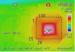
Looking at the thermography of the board, only the microcomputer had a fever.

So I guess that we are consuming electricity with the microcomputer.

However, I am in trouble because I do not know the cause.

Could you give me some advice?

◆ Phenomenon Environment

Phenomenon board: customer board
Consumption current: 13 mA to 50 mA max
Theoretical consumption current of board: 15uA

◆ Unused pin processing

All unused pins are set to Low output setting (PxDIR.y = 1, PxOUT.y = 0)

◆ Symptom situation

The microcomputer's operation was normal even on boards with high current consumption.
If reset input is made to the reset terminal, consumption current may become about 15 uA.

Consumption current is high right after power on.
Especially this phenomenon is easy to occur if it is a new battery.

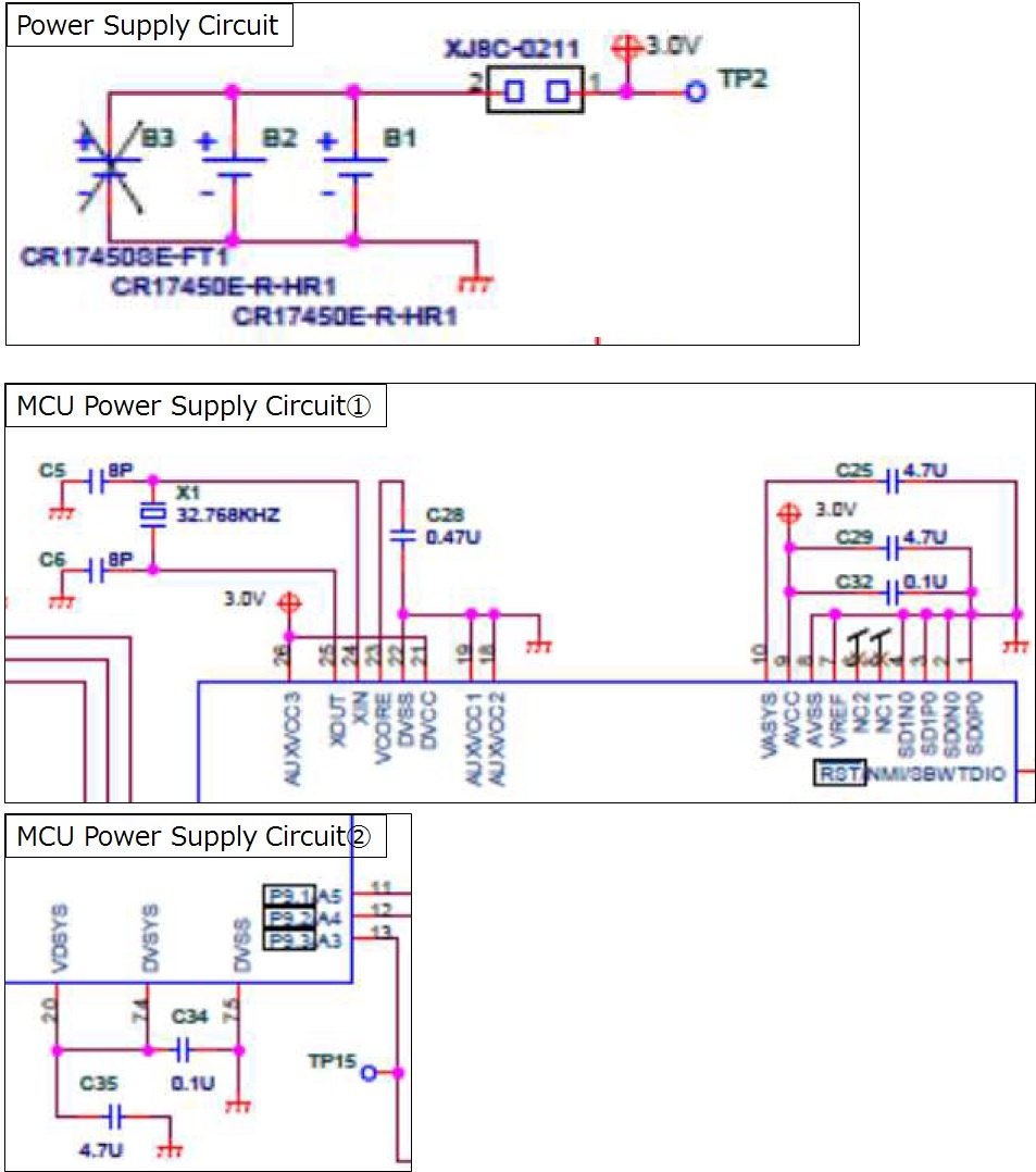
◆ Circuit diagram

The circuit diagram around the power supply is as follows:

Batteries are connected directly to microcontroller, peripheral circuit Vcc.
battery:Cell Type CR17335E-R

◆ Thermography image

Best regards.

Cruijff

  • Hello,

    This is a bit unusual as the MSP30 should not get that hot nor draw that much current. Max current form DVCC should be 20mA and AVCC 10mA so 50mA is way too high. (Always check datasheet for your part for most accurate numbers.)

    A few questions and suggestions.

    How are you measuring current? Is this from the power input to the board, or is this at DVCC of the chip? to get the most accurate current consumption number that the MSP430 is using, you need to measure from the DVCC trace by the MSP430.

    How many boards see this issue?

    Have you tried programming in an LPM3 example code on the device to see if the issue still persists? This example can be found within MSP430Ware. MSP430Ware is found within TI Rsource Explorer in CCS or at the cloud site linked here: dev.ti.com/.../

    Typically, when I've seen similar issues, the cause was either a ESD damaged part, or a short from VCC-GND somewhere (either by improper soldering or design flaw) that causes damage to the part. One way to test for this is to do an A-B-A swap of chip and board. So take a known working board + chip and switch it with a known "bad" board + chip. You end up with good board + "bad" chip, and "bad" board + good chip and see if the issue follows the chip or the board. If the error goes away, then its typically a soldering issue.
  • From your description on the behavior when MCU is reset, I believe the current to be related to an I/O short (i.e. IO is low but is somehow connected to a VCC on the external circuit by mistake). To confirm this, change all unused IOs to input direction with all pull up/down resistors disabled.
  • Hi Cruijff,

    I hope Jace and Mike are right.
    I have observed that ESD damaged MCU could consume 20-50 mA and still be able to properly execute program code.
  • Hi All,

    Thank you for your reply!
    I'll answer a few questions.

    How are you measuring current? Is this from the power input to the board, or is this at DVCC of the chip?

    It is measured with the current from the power supply input to the board.
    When measuring the temperature of the board with thermography, MSP430 was the most feverish, so I suspected MSP430.

    How many boards see this issue?

    It is 10 boards out of 56 boards.

    However, we are also in trouble because the board will not necessarily cause phenomena.

    Have you tried programming in an LPM3 example code on the device to see if the issue still persists?
    A-B-A swap
    I/O short

    I have not tried it yet so I will check it.


    Can you confirm the following additionally?

    Looking at the thermography, the temperature of Pin No. 20 to 30 is relatively high.


    · Is there a possibility that current may flow internally depending on the reset or power supply OFF / ON timing at PMM setting?
    · Is there a possibility that the AUX Vcc 1 to 3 are connected internally due to the reset or power supply OFF / ON timing and the state of current flowing?

    The more new a battery is, this phenomenon is more likely to occur.
    (It is hard to occur if it is a slightly used battery.)
    Do you have any knowledge as to whether large current flows depend on battery condition?

    Best regards.

    Cruijff

  • Edit: A portion of this message was given in error and has been corrected in the replies below. I have stricken through the incorrect information, please disregard if you are looking at this post. 

    Hello Cruijff,

    Measuring current from the input to the board will not get an accurate picture of what the MSP430 is using. You will need to cut the DVCC trace right by the MSP430 and measure there for the most accurate current consumption numbers the MSP430 is using.

    After further review, i think I know your issue. I see that you are not using AUXVCC1 and AUXVCC2. Since these are not being used, they need to be connected toy our DVCC line. AUXVCC1/2 are auxiliary inputs for power and will be connected internally to the power plane. Try cutting the ground connection on these pins and connecting to DVCC.

  • Hi Jace,

    Thank you for you reply!

    I'd like to ask you about additional AUXVCC.

    According to User's Guide (SLAU 208Q P133), the following is written:

    • Any unused auxiliary supply inputs (AUXVCC1 or AUXVCC2) must be connected to DVSS.
    • If AUXVCC1 or AUXVCC2 are unused, they should be disabled by setting AUXxMD = 1 and AUXxOK = 0 in software, too.

    As in the user's guide, AUXxMD = 1 and AUXxOK = 0 was set with software.

    However, a large current flowed.

    Is the way of User's Guide wrong?

    Is DVCC the preferred method?

    Best regards.

    Cruijff

  • Cruijff,

    sorry for the confusion there. In my haste to answer our question I misread. The User Guide is correct, they should be connected to DVSS is not used. Please disregard, my earlier statement. my apologies.

    With that being the case, Testing an LPM3 example with direct measurement of the MSP430 power consumption should be your next test.

    After that, the A-B-A chip swap commented about earlier would be the next test.
  • Hi Jace,

    Thank you for pointing out!
    I understood that there is no problem with the setting of the user's guide.

    I tried also the sample code of LPM 3 and the result was as follows.

    MSP-TS430PZ100B Customer's Board
    LPM3 example No phenomena phenomena occurence
    Customer's Code No phenomena phenomena occurence

    Anomalous current flowed even at LPM3.

    I tried various tests, it turned out that it does not occur when adding 10 μF or more capacitor of the power supply line.

    I think that Errata "AUXPMM2" is doubtful from this.
    Please let me know if there are any items to point out.

    Best regards.

    Cruijff

  • Cruijff,

    It is recommended to have a 10uF cap on the DVCC line as well as a 1uF cap closer tot he chip on DVCC for power stability reasons. I should of noticed this earlier from your schematic snippets, but had assumed you had them and were not showing. My bad. With this information, my guess is the part is going into an out of spec state, most likely frequency vs voltage violation , due to a small increase of current draw the decreases the voltage supplied just enough to enter this state. It then snowballs from there. The power stability caps help prevent this by giving a buffer between the power source and the chip.

**Attention** This is a public forum