This thread has been locked.

If you have a related question, please click the "Ask a related question" button in the top right corner. The newly created question will be automatically linked to this question.

MSP430F47177: USCIAB0RX , USCIAB0TX , USCIAB1RX , USCIAB1TX - MSP430 INTERRUPTS

Part Number: MSP430F47177


Hello,

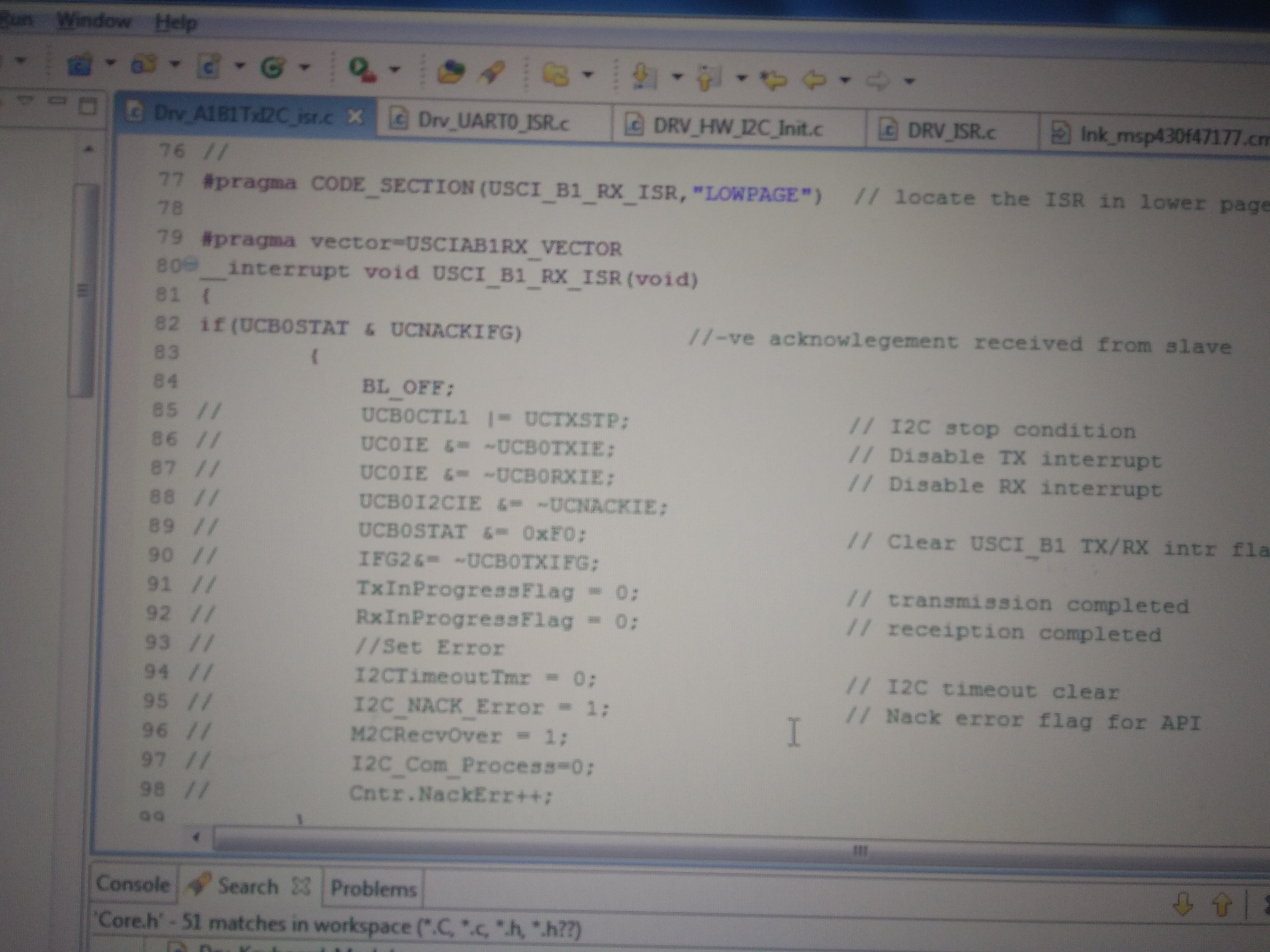
i'm wondering when the FOUR  ISR are triggered:

USCIAB0TX_VECTOR

USCIAB0RX_VECTOR

USCIAB1TX_VECTOR

USCIAB1RX_VECTOR

Couldn't find any Information about that.

Kindly help

Thank you.

Regards,

Sameer Batra 

  • There is one interrupt vector to handle the TX events of two USCI modules (A and B), and one interrupt vector to handle the RX events of two modules; see section 19.3.16 of the User's Guide.

    The F47177 has four USCI modules (A0/B0/A1/B1), so it needs four vectors. The gcc header file says:

    #define USCIAB1TX_VECTOR        (19)                     /* 0xFFE4 USCI A1/B1 Transmit */
    #define USCIAB1RX_VECTOR        (20)                     /* 0xFFE6 USCI A1/B1 Receive */
    ...
    #define USCIAB0TX_VECTOR        (25)                     /* 0xFFF0 USCI A0/B0 Transmit */
    #define USCIAB0RX_VECTOR        (26)                     /* 0xFFF2 USCI A0/B0 Receive */
    
  • Dear Clemens, 

    Thanks for your quick response .

    As u said the following :

    The F4777 has four USCI modules (A0/B0/A1/B1), so it needs four vectors. The gcc header file says:

    #define USCIAB1TX_VECTOR        (19)                     /* 0xFFE4 USCI A1/B1 Transmit */
    #define USCIAB1RX_VECTOR        (20)                     /* 0xFFE6 USCI A1/B1 Receive */
    ...
    #define USCIAB0TX_VECTOR        (25)                     /* 0xFFF0 USCI A0/B0 Transmit */
    #define USCIAB0RX_VECTOR        (26)                     /* 0xFFF2 USCI A0/B0 Receive */
    I am posting some part of my code . I am confused that where should I write the Interrupt Routine when the not acknowledgement Interrupt Flag is set .
    From the Datasheet and User manual i came to know that USCI _A0 & USCI_A1 Provide support for SPI , UART , IrDA . And USCI_B0 & USCI_ B1 Provide support for SPI and I2C . 
    My question are  : 
     
    1 - Which Vector is needed when Not Acknowledgement Interrupt flag is set .
    2- where should i write the interrupt service routine when negative Acknowledgment  bit is set .
    As the datasheet say's to USE USB0 & USB1 for I2C i wrote : 
    #Pragma Code_Section(USCIABTRX_ISR,"LOWPAGE")
    #Pragma Vector = USCIAB1RX_VECTOR 
    ___intrrupt void USCIAB0RX_ISR(void)
    {
    if (UCNACKIFG & UCB0STAT
     {
        UCBOCTL | = UCTXSTP     // stop I2C
    }
    }
    Kindly help !
    Regards , 
    Sameer Batra 
  • Section 21.3.7 of the User's Manual says:

    USCI_Ax and USCI_Bx share the same interrupt vectors. In I2C mode the state change interrupt flags UCSTTIFG, UCSTPIFG, UCNACKIFG, UCALIFG from USCI_Bx and UCAxRXIFG from USCI_Ax are routed to one interrupt vector. The I2C transmit and receive interrupt flags UCBxTXIFG and UCBxRXIFG from USCI_Bx and UCAxTXIFG from USCI_Ax share another interrupt vector.

    (See page 21-25.)

    The I²C state change interrupts go the same vector that handles Ax Receive.

  • Thanks for the Information clemens,

    Now i have wrote the Interrupt routine for the Negative Acknowledgement but now i am facing the linking error . 

    for the reference i am attaching the screen shot of the code and the error respectively . 

    CODE :

    ERROR :

    kindly help ,


    Regards ,

    Sameer Batra 


  • Do not use screenshots for text that can simply be copied/pasted.

    That error typically happens when you have declared multiple interrupt handlers for the same vector.
  • Thanks for the information .

**Attention** This is a public forum