This thread has been locked.

If you have a related question, please click the "Ask a related question" button in the top right corner. The newly created question will be automatically linked to this question.

MSP430F5249: Clock setup using driverlib

Part Number: MSP430F5249
Other Parts Discussed in Thread: MSP-TS430RGC64C, MSP-FET

MSP430 Team,

A weird problem.  I am using F5249 device in the MSP-TS430RGC64C board and having trouble setting up the clocks.  I am using driverlib to set MCLK to 25 MHz, and ACLK=REFO=32768 Hz.  Here is my code:

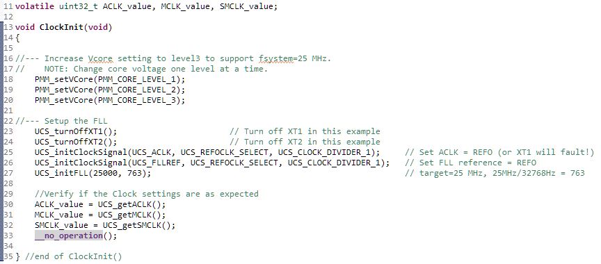
I am also measuring MCLK on a scope.  The problem is the code is only working correctly if I set a breakpoint at the __no_operation() (and then continue execution).  With or without the breakpoint, ACLK_value and MCLK_value are correct (ACLK_value=32768, MCLK_value=24969216).  But, without the breakpoint, the scope shows MCLK of about 8.1 MHz.  With the breakpoint the scope shows MCLK of 25 MHz.

Any idea what is going on here?  I've been debugging this for a while, but can't find the problem.

Thanks and regards,

David

  • The FLL needs some time to adjust the frequency. Use UCS_initFLLSettle() to wait for it.

    PMM_setVCore() automatically increases the level in multiple steps.
  • I've resolved the problem for now. It is related to entering a low-power mode in my main loop.

    - David
  • Clemens Ladisch said:
    The FLL needs some time to adjust the frequency. Use UCS_initFLLSettle() to wait for it.

    PMM_setVCore() automatically increases the level in multiple steps.

    Clemens,
    Thank you for responding.  The PMM_setVCore() is good.  I had ported over non-DriverLib code that increased the level one at a time.  I didn't read DriverLib carefully here.
    On the UCS_initFLLSettle(), that simply adds a timeout to the UCS fault check loop.  UCS_initFLL() will loop forever until all faults are gone.
    It's kind of weird that I removed the LPM3 entry from my main loop and now things are working.  For my purposes, this is good enough right now.
  • The FLL does not run in LPM3, so the DCO stayed at whatever frequency it had reached at that moment.
  • Hi David,

    I'm glad to hear that this has been solved now.
    One last comment from my side would be that measuring the clocks during and active debug session might also cause a problem. So you could also check if the issue can still be seen without the MSP-FET connected.

    As you've stated that it's working for your purposes I will go ahead and close this thread.
    Please reply to re-open in case there are other pending questions.

    Thanks and best regards,
    Britta
  • Britta,

    There is still something strange here, and I did not want to just move on and ignor it.  My full code is pretty simple.  Initialize the clocks, setup a timer interrupt, and enter LPM3.  In the timer ISR I send something out the USCI_A0_UART.  I actually noticed the problem because the UART communication was failing.  I traced the issue to the wrong clock frequency coming out of the DCO/FLL (and hence the UART was at the wrong baud rate).  This happens with or without the debugger connected.

    I replaced the driverlib clock initialization with manual configuration, and the problem went away.  The main difference was an extra delay loop in the manual setup before polling for oscillator fault.  If I go back to the driverlib version and add the same delay after the call to UCS_initFLL(), the driverlib version works.  Alternately, if I remove the __delay_cycles(782000L) from the manual version of the FLL setup, it too fails (that is, MCLK is wrong is the UART comms fails).

    I can also look at the MCLK output signal on P4.7.  If I disable interrupts and halt the debugger (while in LPM3), the MCLK signal is dead (flat lined) which is to be expected because the DCO is off.  So far so good.

    If I set a breakpoint in the timer ISR however, I can see the MCLK is incorrect without the delay for both the driverlib and manual config versions.

    So why do we need this delay?  I took the delay from the TI examples for the F524x devices.

    I can send my CCS project if you want to go that route.

    Regards,

    David

  • Hi David,

    thank you for elaborating on this.
    I'd like to reproduce your findings with other hardware to see if there is indeed a software issue related to the driverlib examples.
    If I understood you correctly you said that the issue is present when using the exact example from the latest driverlib version, correct? Could you quickly state which exact example you use?
    I'd also appreciate if you could send your CCS project for me to test. I'd then come back to you to discuss my findings.

    Thanks and best regards,
    Britta
  • Hi Britta,

    No, I did not use exactly a DriverLib example as the examples do not do what I am doing, specifically enter LPM3 mode after setting up the clocks.

    The problem can be boiled down to a single question to start, and we can get way from DriveLib for now.  In the MSP430F524x software examples SLAC620.f, example msp430F524x_usc_10.c, it initializes the clocks as follows:

    I have done similar in my code.  Now if you enter LPM3 mode for your main loop afterward, the clocks are correct when you exit LPM.  That is, MCLK is 25 MHz.  You can see it on a scope.  But, if you remove the __delay_cycles(782000) statement from the above code, MCLK is not correct.  It is about 7.5 MHz.

    The question is why do you need this delay?  The do{} loop after the delay checks for DCOFFG faults.  If the DCO was not stabilized, you would continue looping here until it is.  Right?

    EDIT: OK, I read more and see the DCOFFG flag is only set when the DCOx is set to either 0 or 31.  It is not detecting stabilization of the DCO but rather endpoint settings.  Still, even without the delay the FLL should eventually stabilize at 25 MHz.  It doesn't.  It never recovers once you enter LPM3 the first time.

    END_EDIT

    The lack of the delay is why DriverLib fails to work correctly when I enter LPM3 mode as my main loop.  DriverLib does not have this extra delay in the function UCS_initFLL().  So we could ask why DriverLib doesn't have the delay if it is required.

    I have attached my CCSv8.1 project.  As it is configured now, it uses manual configuration of the clocks (not DriverLib), and I left the delay in there.  So, everything works.  You can observe MCLK on a scope at pin P4.7 as 25 MHz.  Now go in to clocks.c and comment out that delay.  When you run the code now, MCLK is about 7.5 MHz.  Realize that I am spending much of the time in LPM3 here where MCLK is inactive.  The scope triggers off MCLK however, so you only see MCLK when it is active.  I have a timer that is waking the system up at a 2 Hz rate.

    MSP430F5249_UsciA0_UART_DriverLib_2018Aug24.zip

    Regards,

    David

  • I have figured out the problem.  Clemens was close to spot on.  The FLL does not operate in LPM3.  We know that.  But what I didn't realize is that the FLL does not start upon exit from LPM3 unless you manually clear the SCG0 bit in the SR register.  I spotted this in the 5xx User's Guide, SLAU208q:

    5.2.10 FLL Operation From Low-Power Modes
    An interrupt service request clears SCG1, CPUOFF, and OSCOFF if set, but does not clear SCG0. This
    means that for FLL operation from within an interrupt service routine entered from LPM1, LPM3, or LPM4,
    the FLL remains disabled and the DCO operates at the previous setting as defined in UCSCTL0 and
    UCSCTL1. SCG0 can be cleared by user software if FLL operation is required.

    So in my ISR I cleared SCG0 which started up the FLL again.

    What was going on here was I was entering LPM3 soon after configuring the clocks.  The FLL had not yet locked, so as Clemens mentioned the DCO ran at whatever setting it happened to be at when I exited LPM3.  By starting the FLL again in the ISR, the DCO continued to be adjusted (until I went back into LPM3 after the ISR).  The ISR is actually pretty short, and it took a couple of executions of the ISR before the FLL locked on to the correct frequency.  You could see this in the UART communication (I got several wrong receive characters until I finally was communicating correctly).

    This is actually a pretty subtle issue, especially with DriverLib which does not add a delay after enabling the FLL.

    I will close this thread.


    Regards,

    David

  • Hi David,

    thanks again for posting your findings here.
    I'm glad you've worked it out but understand that this is tricky. I'll see if it makes sense to somehow further highlight this in our documentation.
    Thank you for sharing this with the E2E community. I'm sure it will help other running into the same issue.

    Best regards,
    Britta

**Attention** This is a public forum