This thread has been locked.

If you have a related question, please click the "Ask a related question" button in the top right corner. The newly created question will be automatically linked to this question.

MSP430F5338: I2C slave not responding to ACLK.

Part Number: MSP430F5338
Other Parts Discussed in Thread: TMP75

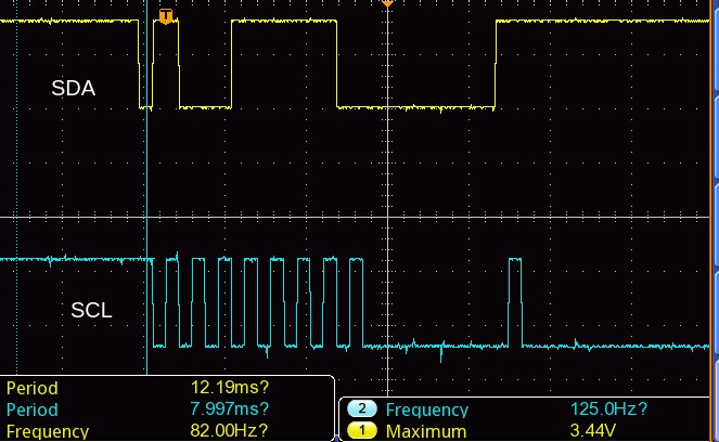
We are using a TMP75 temperature sensor as a slave to our MSP430F5338. I have configured with the code which was given as example to configure ACLK as input to the I2C line. We are facing issues when probing the SCL and SDA lines with different behaviour of single switch of the clock from high to low once or no response at all. Tried configuring with FLL and without FLL. The input clock given in XT1 is through a crystal oscillator operating at 32 Khz. 

Configuring ACLK

void ConfigXT1(void)

{
P7SEL |= BIT0 + BIT1; //XT1IN, XT1OUT
UCSCTL4 |= SELA__XT1CLK;
UCSCTL6 &= ~(XT1OFF);
UCSCTL6 |= (XT1DRIVE0_L | XT1DRIVE1_L);
UCSCTL6 &= ~(XT1BYPASS|XTS);
do {
UCSCTL7 &= ~(XT1LFOFFG);
// Clear XT2,XT1,DCO fault flags
SFRIFG1 &= ~OFIFG; // Clear fault flags
} while( UCSCTL7 & XT1LFOFFG );
}

Configuring the I2C slave

P2SEL |= BIT1 + BIT2;

UCB0CTL1 |= UCSWRST; // Enable SW reset

UCB0CTL0 = 0x00;

UCB0CTL0 |= UCMST + UCMODE_3 + UCSYNC;

UCB0CTL1 |= UCSSEL_1;
//UCB0BR0 = 80;
//UCB0BR1 = 0; // Clear SW reset
UCB0CTL0 &= ~UCSLA10;
UCB0CTL1 &= ~UCSWRST;
UCB0I2CSA |= 0x4f;
UCB0IE |= (UCTXIE | UCRXIE) ; // Enable TX interrupt
__bis_SR_register(GIE);

  • I'm not quite sure what you're describing. Do you see a Start pulse and nothing more? Or no activity at all? Do you have a scope trace?

    If you're suspicious of your ACLK, I would suggest:
    1) Try running the I2C using SMCLK (with a suitable BR0 value) and see if it's different.
    2) Configure P1.0 to output ACLK and check it on a scope

    How are the TMP75 address pins (A0-A2) configured?
  • Hi Mohammed Zakariya,
    I went through your configuration and I couldn't find anything implausible.
    You can skip "UCB0CTL0 &= ~UCSLA10;" since you're clearing UCB0CTL0 a few lines prior, but it doesn't hurt to keep this in as long as this is not time critical.
    You are only showing the initializations in the snippet above, so I hope you write to the TX buffer elsewhere in your code to actually start a I2C transmission.
    I agree with Bruce that it makes sense to check if ACLK clock source works properly.

    Please let me know if that helps to find the root cause.
  • Thanks for replying,  

    1) Try running the I2C using SMCLK (with a suitable BR0 value) and see if it's different.

    1. On using the SMCLK with the crystal oscillator operating at 16 MHz and using the DCO to output it at 8MHz the following waveform was observed,

    the BR0 value given was 80, to get a clock of 100 Khz

    On without giving any value for prescaling on giving 8Mhz, I am getting an unusual behaviour with the clock as follows, the obtained frequency in SCL is 125 hz

    This was the obtained behaviour on configuring with SMCLK.  

    2) Configure P1.0 to output ACLK and check it on a scope

    Sorry this will not be possible to do ,The module currently in use is doesn't have a pin out and there are no test points on the ACLK and SMCLK pins respectively.

  • Hi Maximilian Albrecht,

    Thanks for replying, sorry that I didn't attach the I2C function, I am attaching it along with this reply. This function issues the start bit and the purpose it serves is to receive two bytes


    void receive_i2c(unsigned char byteCount, unsigned char data){
    {
    *TI_transmit_field = data;
    unsigned char RX_Data[2];
    byteCtr = byteCount;

    UCB0CTL1 |= UCTR | UCTXSTT;

    while(!(UCB0IFG & UCTXIFG));

    UCB0TXBUF = data;

    while(!(UCB0IFG & UCTXIFG)); // Wait for Tx flag to be set

    UCB0CTLW0 &= ~UCTR; //Repeated start condition
    UCB0CTLW0 |= UCTXSTT;

    while(!(UCB0IFG & UCRXIFG)); // Wait for Rx flag to be set

    RX_Data[0] = UCB0RXBUF;
    while(!(UCB0IFG & UCRXIFG));

    RX_Data[1] = UCB0RXBUF;
    UCB0CTLW0 |= UCTXNACK;
    UCB0CTLW0 |= UCTXSTP;

    while(!(UCB0IFG & UCSTPIFG)); // Wait for stop flag to be set
    }

    I have explained in a reply to Bruce that we currently don't have the provision to see the ACLK or SMCLK. Please put forward your inputs after reviewing. Thanks in advance.
  • Hi Mohammed Zakariya,

    Can you confirm that you have applied pull-up resistors at SCL and SDA lines? Since there seem to be no quicker clock than 125 hz that might indicate that the port is not pulled to high between clock pulses..?

    Best regards,
    Max
  • > UCB0IE |= (UCTXIE | UCRXIE) ; // Enable TX interrupt
    You're enabling these interrupts, but I don't see an ISR. Your receive_i2c function seems to not expect them to be set.

    My guess is that your program is resetting (or worse) after sending the address byte (TXIFG), and that's why SCL is going "dead". I recommend you remove that line.

    [Edit: Actually, if you're using a recent version of CCS your program is probably spinning in ISR_fault, i.e. it's not restarting.]

  • Hi Mohammed Zakariya,

    We haven't heard back from you, have you been able to solve the issue? If, yes it would be nice if you could share the solution with us.

    Thanks and best regards,
    Max

**Attention** This is a public forum