This thread has been locked.

If you have a related question, please click the "Ask a related question" button in the top right corner. The newly created question will be automatically linked to this question.

CCS/MSP430FR2355: Measured Time Period for a Timer Delay doesn't match the Expected Value

Part Number: MSP430FR2355

Tool/software: Code Composer Studio

Hello,

I wrote the following code below to get MSP430 to go into LPM3 and then wake up through a timer interrupt. I give different values to the timer each time it goes to sleep mode. The frequency (both Main clock and Aux clock) is 10kHz so I expect the sleep period to be 1s, 2s, 3s, 4s and 5s in that order. 

I'm measuring this by measuring the current on a digital multimeter which samples every 40us. I use the significantly high active mode current to figure out the delay (during which the device was in LPM3 and consumed much lower current) and the numbers I get are 1.1s, 2.2s, 2.6s, 3.2s and 4.2s. The multimeter was connected between the power supply and the microcontroller. 

I used the debug mode to see what was happening to the registers and despite setting the clear flag, it doesn't look like it actually gets set in the TB0CTL register. Also, every time I enter or exit LPM3, the TB0CTL register changes - I'm unsure if that is expected to happen or not. The values I see in the TB0R register immediately after the timer interrupt seems very random too. It was taking too long on debug mode so I changed the values on the TB0CCR0 register to be 10, 20, 30, 40 and 50 instead of 10000, 20000 and so on (to be able to test it). When I switch back to the original numbers (the ones in the code below), TB0R doesn't seem to take any of these bigger values, I only see it go to 26 at some point in the middle and was surprisingly quick unlike the first time I tried it.

I'm unsure where the error is right now. Essentially I want to be able to reset the TB0R register every time I start a new count and I want to be able to see that count when I plot the current - I'm unsure where I'm going wrong with this. 

Any help, or prod in the right direction would be greatly appreciated. 

Here's the code that I'm using:

#include <msp430.h>

int num_packets = 0, j, count;

void main(void)
{
WDTCTL = WDTPW | WDTHOLD; // Stop watchdog timer

CSCTL4 = SELA__VLOCLK | SELMS__VLOCLK;

PM5CTL0 &= ~LOCKLPM5; // Disable the GPIO power-on default high-impedance mode
// to activate previously configured port settings

P1OUT = 0x00; P2OUT = 0x00;
P3OUT = 0x00; P4OUT = 0x00;
P5OUT = 0x00; P6OUT = 0x00;

P1DIR = 0xff; P2DIR = 0xff;
P3DIR = 0xff; P4DIR = 0xff;
P5DIR = 0xff; P6DIR = 0xff;

// P1DIR |= BIT0;
// P1OUT |= BIT0;

//Set timer
TB0CCTL0 = CCIE | CLLD_0; //Added CLLD bits

// TB0CTL = MC_1|ID_0|TBSSEL_1|TBCLR; //set up timer and start it
TB0CTL = ID_0|TBSSEL_1|TBCLR;
TB0R = 0x0;
TB0CCR0 = 10000;
TB0CTL |= MC_1;
__bis_SR_register(LPM3_bits | GIE);


TB0CTL = ID_0|TBSSEL_1|TBCLR;
TB0R = 0x0;
TB0CCR0 = 20000;
TB0CTL |= MC_1;
__bis_SR_register(LPM3_bits | GIE);

TB0CTL = ID_0|TBSSEL_1|TBCLR;
TB0R = 0x0;
TB0CCR0 = 30000;
TB0CTL |= MC_1;
__bis_SR_register(LPM3_bits | GIE);

TB0CTL = ID_0|TBSSEL_1|TBCLR;
TB0R = 0x0;
TB0CCR0 = 40000;
TB0CTL |= MC_1;
__bis_SR_register(LPM3_bits | GIE);

TB0CTL = ID_0|TBSSEL_1|TBCLR;
TB0R = 0x0;
TB0CCR0 = 50000;
TB0CTL |= MC_1;
__bis_SR_register(LPM3_bits | GIE);

/*
for(num_packets = 0; num_packets < 5; num_packets++)
{
TB0CTL = MC_1|ID_0|TBSSEL_1|TBCLR; //set up timer and start it
// P1OUT &= ~BIT0;
//enter lpm3
TB0CCR0 = 10000*(num_packets + 1); // Set Timer Period
__bis_SR_register(LPM3_bits | GIE);
__no_operation();
}
*/
// P1OUT = 1;
}


#pragma vector = TIMER0_B0_VECTOR
__interrupt void TB0_ISR (void)
{
__bic_SR_register_on_exit(LPM3_bits | GIE);
TB0CTL &= ~MC_3; // Turn off Timer - edited from ~MC_1 to ~MC_3 so that the MC bits go to 00
}

Thanks,

Yaman

  • 1) The TBCLR bit clears by itself. You won't be able to see it =1, either in the debugger or in your program.
    2) TB0R continues counting while you're at a breakpoint, until you set MC=0. Depending on when you look, you may see this.
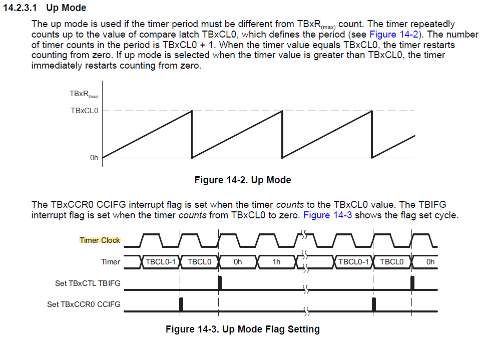
    3) Setting TB0R=10000 when TB0CCR0=10 (in Up mode) causes TB0R to wrap to 0. [Ref User Guide (SLAU445H) Sec. 14.2.3.1.1]
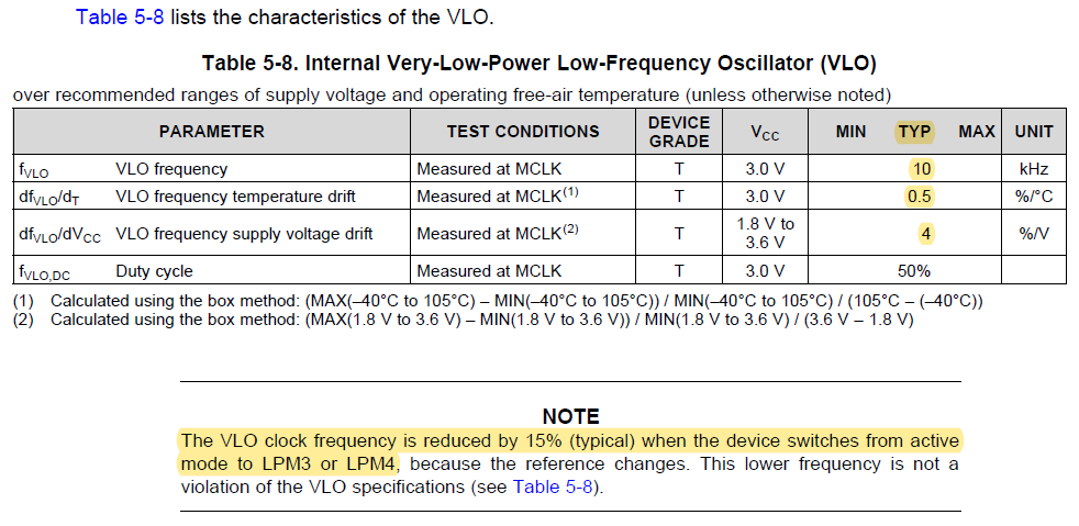
    4) VLOCLK has quite a lot of tolerance -- +/- 50% per data sheet (SLASEC4B) Table 6-9. So unless you measure/calibrate VLOCLK first I wouldn't expect your timings to match wall-clock time. I'm pretty sure that over short periods it doesn't vary much, so I would expect the successive timings to be proportional, which makes your "2.6" measurement look a bit odd. Is your DMM really responsive enough to measure like that? (Mine isn't.)
  • Hi Bruce,

    Thank you for the prompt reply!

    I do understand that TB0R continues counting but I would expect it to increment by 1 with each command and I don't really see that. I'll give you the exact values I see tomorrow once I am back in my office. Moreover, at the point of the occurrence of the interrupt, I would expect it to be at its peak value - would that be correct to say?

    The only time I set a value for TB0R is when I make it 0 and I do that right before setting TB0CCR0 to the timer value I want it to have. Other than that, at no point am I changing anything as far as TB0R is concerned. I wasn't sure if it was getting reset before starting the next iteration of the timer so I was doing it manually as well. 

    The DMM is responsive - it has been set to sample every 40us and I'll likely be able to get it to go down to 20us. That should give us enough accuracy to be able to measure with a small error percentage. My initial thought was that TB0R wasn't getting reset and the timer was incrementally counting up and the 2.6 measurement was when it overflows and that probably causes an interrupt. I don't know if that's right either and I'm unsure on how to debug from here and figure out what's happening. 

    Do the settings os the timer registers look right to you?

    Please let me know if there is any more information I can provide. Thanks again, Bruce!

  • Hi Yaman,

    Bruce has already offered a great post, but please let me add more details.

    Firstly, according to MSP430FR235x, MSP430FR215x Mixed-Signal Microcontrollers datasheet, you can easily find that VLO is not accurate enough for your application. It is strongly recommended to use XT1 oscillator crystal instead, since it is much more accurate and also low-power at the same time.

    Secondly, in the MSP430FR4xx and MSP430FR2xx Family User's Guide, you can find the detailed description of TBCLR. You can see that setting TBCLR clears TBxR, so it is unnecessary to write TB0R = 0.

    Last but not least, a friendly advice just for your reference: rather than using a DMM, maybe you can also consider another approach by using one oscilloscope. Configure one oscilloscope channel to be triggered by a falling edge with "Single" mode. Upon timer interrupt, you can toggle one MSP430 GPIO, and with oscilloscope you can capture that event easily and accurately. Certainly with this approach error still exists, and in order to minimize the error, you can leave the SELMS to the default option SELMS__DCOCLKDIV. Given the condition of LPM3, it is unnecessary to set SELMS to SELMS__VLOCLK because MCLK and SMCLK are off under LPM3.

    I have modified you code to serve as an example for your reference. Hope it helps!

    #include <msp430.h>
    
    void main(void) {
        WDTCTL = WDTPW | WDTHOLD; // Stop watchdog timer
        PM5CTL0 &= ~LOCKLPM5; // Disable the GPIO power-on default high-impedance mode
        // to activate previously configured port settings
    
        P1OUT = 0x00;
        P2OUT = 0x00;
        P3OUT = 0x00;
        P4OUT = 0x00;
        P5OUT = 0x00;
        P6OUT = 0x00;
    
        P1DIR = 0xff;
        P2DIR = 0xff;
        P3DIR = 0xff;
        P4DIR = 0xff;
        P5DIR = 0xff;
        P6DIR = 0xff;
    
        P2SEL1 |= BIT6 | BIT7;                  // P2.6~P2.7: crystal pins
        do
        {
            CSCTL7 &= ~(XT1OFFG | DCOFFG);      // Clear XT1 and DCO fault flag
            SFRIFG1 &= ~OFIFG;
        } while (SFRIFG1 & OFIFG);              // Test oscillator fault flag
    
        CSCTL4 = SELA__XT1CLK | SELMS__DCOCLKDIV;
    
        //Set timer
        TB0CCTL0 |= CCIE;                   // TBCCR0 interrupt enabled
    
        P1OUT |= BIT0;                              // Used as indicator
    
        TB0CCR0 = (32768 / 4) * 1 - 1;              // 1s
        TB0CTL = TBCLR;                             // Clear Timer
        TB0CTL = ID__4 | TBSSEL__ACLK | MC__UP;     // Input divider /4, ACLK, UP mode
        P1OUT ^= BIT0;                              // Indicating timer start
        __bis_SR_register(LPM3_bits | GIE);         // Enter LPM3 w/ interrupt
        __no_operation();                           // For debug use
    
        TB0CCR0 = (32768 / 4) * 2 - 1;              // 2s
        TB0CTL = TBCLR;                             // Clear Timer
        TB0CTL = ID__4 | TBSSEL__ACLK | MC__UP;     // Input divider /4, ACLK, UP mode
        P1OUT ^= BIT0;                              // Indicating timer start
        __bis_SR_register(LPM3_bits | GIE);         // Enter LPM3 w/ interrupt
        __no_operation();                           // For debug use
    
        TB0CCR0 = (32768 / 4) * 3 - 1;              // 3s
        TB0CTL = TBCLR;                             // Clear Timer
        TB0CTL = ID__4 | TBSSEL__ACLK | MC__UP;     // Input divider /4, ACLK, UP mode
        P1OUT ^= BIT0;                              // Indicating timer start
        __bis_SR_register(LPM3_bits | GIE);         // Enter LPM3 w/ interrupt
        __no_operation();                           // For debug use
    
        TB0CCR0 = (32768 / 4) * 4 - 1;              // 4s
        TB0CTL = TBCLR;                             // Clear Timer
        TB0CTL = ID__4 | TBSSEL__ACLK | MC__UP;     // Input divider /4, ACLK, UP mode
        P1OUT ^= BIT0;                              // Indicating timer start
        __bis_SR_register(LPM3_bits | GIE);         // Enter LPM3 w/ interrupt
        __no_operation();                           // For debug use
    
        TB0CCR0 = (32768 / 4) * 5 - 1;              // 5s
        TB0CTL = TBCLR;                             // Clear Timer
        TB0CTL = ID__4 | TBSSEL__ACLK | MC__UP;     // Input divider /4, ACLK, UP mode
        P1OUT ^= BIT0;                              // Indicating timer start
        __bis_SR_register(LPM3_bits | GIE);         // Enter LPM3 w/ interrupt
        __no_operation();                           // For debug use
    
        while(1){
            LPM4;
        }
    }
    
    #pragma vector = TIMER0_B0_VECTOR
    __interrupt void TB0_ISR(void) {
        P1OUT ^= BIT0;   // Indicating interrupt
        __bic_SR_register_on_exit(LPM3_bits | GIE);
    }
    

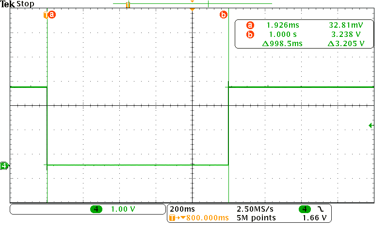
    1s waveform attached below for your reference.

  • Item (3) was in response to:
    > When I switch back to the original numbers (the ones in the code below), TB0R doesn't seem to take any of these bigger values
    ------------------------------
    I'm not quite sure what you mean by "command", but with MCLK=ACLK you should expect 3-5 TB0R ticks for each CPU instruction, and some multiple of that for each code line.
    ------------------------------
    As for seeing it: (a) by the time you reach your ISR probably 15 MCLKs/ACLKs have passed, so by the time your program can look at TB0R it has certainly wrapped and counted up from 0 a little (b) by the time you stop in the debugger some eons have passed and TB0R has cycled multiple times.
    ------------------------------
    > every time I enter or exit LPM3, the TB0CTL register changes
    TBIFG will be set on every cycle. You're clearing it (implicitly) for each test, so I'm guessing that's what you're seeing.
    ------------------------------
    The settings look fine at first glance.
    ------------------------------
    Philo's theory about VLO and LPM3 sounds reasonable -- the effect probably isn't instantaneous and thus has more effect over long periods.
  • Hi Philo and Bruce,

    Thank you for all of your inputs and the code you've given, I'll try it out later today (once I have access to an oscilloscope that is). All of your suggestions make sense and I don't have any further questions about that. An oscilloscope is definitely preferred but I don't have access to one as easily, which is why I was using the multimeter.

    I'll update here with what I find out.

    I do have some questions on the timer, however. The code that I had above, I changed the data fed to the CCR0 register and made it a constant value of 10000. For the 5 times the timer is used, I measure a time of 1.1s, 1.094s, 1.099s, 1.096s and 0.853s. The clock is likely operating at a frequency that's not 10kHz so the measured time isn't 1s which makes sense. The last measurement though doesn't - I'm not able to explain why that happens. I'm going to try the same with a constant value of 20000 and I'll try to set the timer more than 5 times and let you guys know what numbers I see.
    Also, with regards to the TBOR ticks when MCLK = ACLK, why would I see 3-5TB0R ticks for each CPU instruction? Since both the clocks are the same, wouldn't each TBOR tick correspond to a singular CPU instruction?

    The reason for choosing the 10kHz clock was that the current was measured to be 1uA. I'll check the current consumption with the 32KhZ clock, though I do remember Bruce had helped with the LPM mode current and it was around 2 - 3uA. Most likely that should be alright.

    Thanks,

    Yaman
  • > when MCLK = ACLK, why would I see 3-5TB0R ticks for each CPU instruction?
    If you read through User Guide (SLAU445H) section 4.5.2.7, you'll notice that while 1-clock instructions exist, they're the register-register ones that you mostly see in heavy arithmetic. For wiggling pins and setting control registers, the memory-immediate instructions dominate, and they're more like 3-5 clocks (MCLKs).
  • Hi Philo,

    Thank you for the response. I tried the code you gave me - it works perfectly for a delay of 1s and 2s but for the numbers after I have and 2.5s, 3s and 3.7s instead of 3s, 4s and 5s. I wasn't able to get access to a multimeter so I used the DMM set to acquire data at the fastest acquisition.
    When I use the debug mode, however, I see that once TB0R reaches the value set by the CCR0 register, it stays there and doesn't count further. I would expect it to roll back and still keep counting, at least while the ISR is being executed because the MC bits get cleared only after exiting the ISR. Would I be correct in thinking that's how it will work?

    Thanks,
    Yaman
  • Ah yes, that makes sense. Thank you for pointing that out.
  • Hi Philo,
    Just to add to the previous question I posted a few minutes ago, I used the code above but had the CCR0 register set for a 1s timer delay all the 5 times it is used. I see a delay of 1s, 2s, 0.795s, 0.75s and 0.768s.
    I did the same except that I set the CCR0 register to give a delay of 2s each of those times and the values I got were 2s, 2s, 1.535s, 1.55s, and 1.478s.
    I'm unable to explain these numbers because when I check in the debug mode, TB0R seems to be alright, so do all the other registers as far as the set up is concerned. I understand that using the multimeter might give me some error but since the sampling time of the DMM is 40us, I don't expect the error to be as drastic - the difference here is huge which seems like an error in the set up.

    Please let me know if there's any you can help with this - I greatly appreciate anything you can suggest or point me towards.

    Thanks,
    Yaman
  • Hi Yaman,

    With all due respect, I would like to challenge the results taken by DMM. Usually for DMM it's a trade-off between sample speed and resolution. For a typical 6.5-digit DMM, the true resolution at the fastest sample rate usually would be only 3.5-digit at most. In addition, the DMM is usually meant to be used for static measurements, and the sample rate is usually as slow as possible to achieve the best accuracy. As for our signal, which is actually a very fast pulse from P1.0, the DMM is very likely to be not responsive enough. Of course you can refer to the documents of your DMM for details, but generally in this case the results taken by DMM are reasonably unreliable.

    It is strongly recommended to use a better approach rather than the DMM. I can understand your situation where an oscilloscope is unfortunately unavailable (still strongly recommended to get one as soon as possible), and I can offer you one more simple solution: using a MSP430. Only one GPIO and one timer are required. Utilize the interrupt of that GPIO to start or stop the timer. Actually you can use any microcontroller to do it, but as for MSP430 I have created the code below to serve as an example for your reference. When using it, simply connect the P1.0 and GND of both MSP430.

    #include <msp430.h>
    #define NUMBER_OF_TESTS 5
    
    unsigned char i;
    unsigned short int CountVal[NUMBER_OF_TESTS];
    
    int main(void)
    {
        WDTCTL = WDTPW | WDTHOLD;               // Stop watchdog timer
        // Disable the GPIO power-on default high-impedance mode
        // to activate previously configured port settings
        PM5CTL0 &= ~LOCKLPM5;
    
        P2SEL1 |= BIT6 | BIT7;                  // P2.6~P2.7: crystal pins
        do
        {
            CSCTL7 &= ~(XT1OFFG | DCOFFG);      // Clear XT1 and DCO fault flag
            SFRIFG1 &= ~OFIFG;
        } while (SFRIFG1 & OFIFG);              // Test oscillator fault flag
    
        CSCTL4 = SELA__XT1CLK | SELMS__DCOCLKDIV;
    
        P1OUT |= BIT0;                          // Configure P1.0 as pulled-up
        P1REN |= BIT0;                          // P1.0 pull-up register enable
        P1IES |= BIT0;                          // P1.0 interrupt on falling edge
        P1IFG = 0;                              // P1.0 IFG cleared
        P1IE |= BIT0;                           // P1.0 interrupt enabled
    
        for(i = 0; i < NUMBER_OF_TESTS; i++){
            __bis_SR_register(LPM0_bits | GIE); // Enter LPM0 w/interrupt
            __no_operation();                   // For debug
        }
    
        while(1){
            LPM4;
        }
    }
    
    // Port 1 interrupt service routine
    #pragma vector=PORT1_VECTOR
    __interrupt void Port_1(void){
        if(P1IES & BIT0){
            // On falling edge
            TB0CTL = ID__4 | TBSSEL__ACLK | MC__CONTINUOUS; // Input divider /4, ACLK, Continuous mode
            P1IES &= ~BIT0;         // P1.0 interrupt on rising edge
        }
        else{
            // On rising edge
            TB0CTL &= ~MC;          // Stops the timer
            CountVal[i] = TB0R;     // Record timer count value
            TB0CTL = TBCLR;         // Clear Timer
            P1IES |= BIT0;          // P1.0 interrupt on falling edge
            __bic_SR_register_on_exit(LPM0_bits | GIE);
        }
        P1IFG &= ~BIT0;             // P1.0 IFG cleared
    }
    

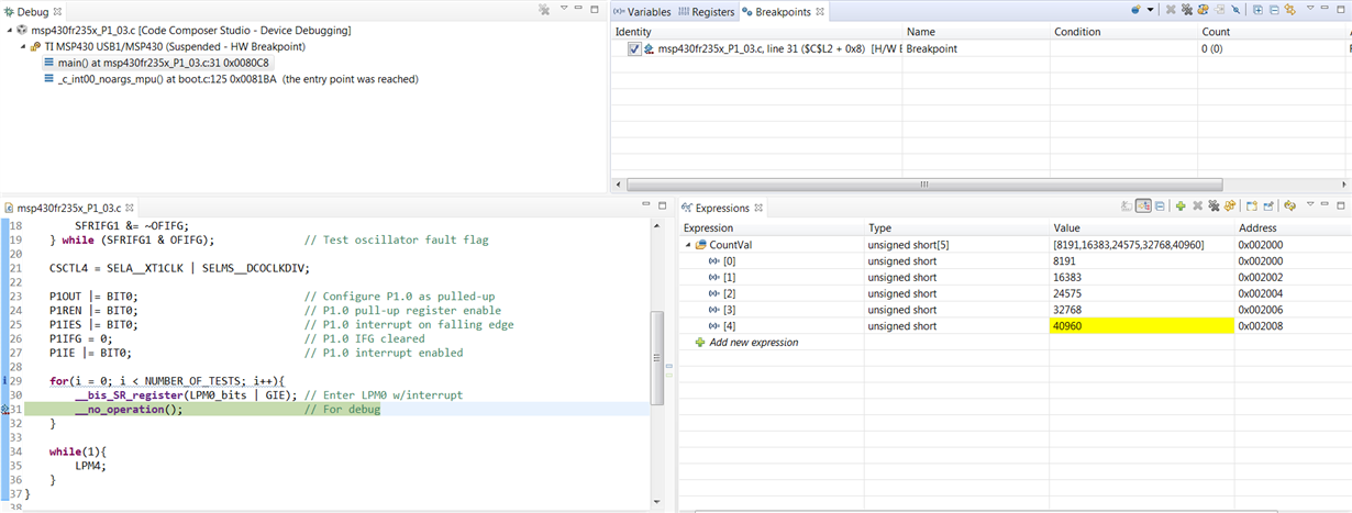
    Correct results attached below for your reference. Hope this one helps!

    By the way, regarding this question:

    Yaman Sangar said:
    When I use the debug mode, however, I see that once TB0R reaches the value set by the CCR0 register, it stays there and doesn't count further. I would expect it to roll back and still keep counting, at least while the ISR is being executed because the MC bits get cleared only after exiting the ISR. Would I be correct in thinking that's how it will work?

    According to MSP430FR4xx and MSP430FR2xx Family User's Guide, the timer count changes at the rising edge of Timer Clock.

    Keep in mind that Timer Clock is 32768Hz, while the CPU clock (MCLK) is 1MHz by default. In this case, Timer Clock is relatively very slow, and the program relatively executes so fast that the timer seems to be not operating at all. If MCLK is not that fast (e.g. when both are 32768Hz by CSCTL4 = SELA__XT1CLK | SELMS__XT1CLK), then you can easily observe the change of timer count.

    However, keep in mind that P1.0 is used as the indicator so that the CPU clock (MCLK) should be as fast as possible to minimize the measurement error (which is interval between the time of timer interrupt and the time of P1.0 going high). In this case, please keep the SELMS to the default option SELMS__DCOCLKDIV.

  • Hi Philo,

    Thank you for the explanation as well as the code. I did see TB0R reach the correct value in the previous code as well so I expected it to work fine. 

    I also agree with you on the point that the multimeter operates on a reduced accuracy when the sampling time is reduced - my thought was that (with the limitations I currently have), trading off reduced accuracy with small enough sampling interval would be alright - I suppose that's not what I am getting. 

    I'll try to get an oscilloscope because I do want to verify that the time intervals are indeed correct - I think it should work out fine. 

    Once again, thanks for being patient and for all the help and explanation, it really helps and I really appreciate it.

**Attention** This is a public forum