


Part Number: MSP432P401R
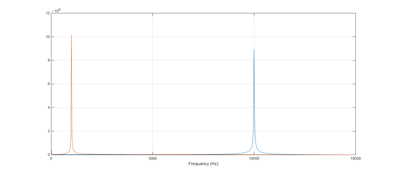
I have been working with the MSP432 in order to sample the data from 12 ADC channels at a constant sampling rate of 30 KSPS per channel, as can be seen in the FFT image of two ADC channel, it was possible to achieve 30 KSPS, two signals, one of 1 KHz and another of 10 KHz where correctly sampled.
Here is the PWM configuration:
#define SAMPLE_CLOCK_FREQUENCY  24000000
#define SAMPLE_FREQEUNCY        360000/*.0f*/

Timer_A_PWMConfig pwmConfig =
{
 .clockSource = TIMER_A_CLOCKSOURCE_SMCLK,
 .clockSourceDivider = TIMER_A_CLOCKSOURCE_DIVIDER_1,
 .timerPeriod = (SAMPLE_CLOCK_FREQUENCY/SAMPLE_FREQEUNCY),
 .compareRegister = TIMER_A_CAPTURECOMPARE_REGISTER_1,
 .compareOutputMode = TIMER_A_OUTPUTMODE_SET_RESET,
 .dutyCycle = (SAMPLE_CLOCK_FREQUENCY/SAMPLE_FREQEUNCY)-19
};
The SAMPLE_FREQUENCY constant is 360000. As a result, the sampling frequency for each ADC channel is 360000/12 = 30 KHz; the problem is that I cannot even double this sampling frequency to 60 KHz. Once I change the SAMPLE_FREQUENCY constant to 360000*2 the FFT figure shows the aliasing of both signals, indicating an incorrect sampling this also happens when I use a SAMPLE_CLOCK_FREQUENCY of 48000000, I am still using the two signals, one of 1 KHz and another of 10 KHz.

In theory, the maximum sampling rate of the MSP432 is 1 MSPS, using 12 channels it should result on a sampling rate of 83333.33 samples per second at each channel, but as can be seen, is not even possible to obtain 60000 samples per second. I am using scatter-gather DMA for sampling. The data is transmitted through serial at a baud rate of 230400; I used a Matlab script that once executed initiates the analog acquisition at the MCU.
How can I solve this issue?is it possible to obtain 1 MSPS while using 12 ADC channels?
In this link you will find the CCS project and the MatLab script:

