This thread has been locked.

If you have a related question, please click the "Ask a related question" button in the top right corner. The newly created question will be automatically linked to this question.

MSP430F5340: MSP430F5340 hangs in while loop while reading data from battery RRC1120 with fuel gauge IC BQ27545G1

Part Number: MSP430F5340

Hi,

I am working with MSP430F5340 controller interfacing with RRC1120 battery which has a BQ27545G1.

I am doing the following steps successfully,

1. Sending start condition

2. Sending address.

3. Sending write bit

4. Sending command

5. Sending start condition

6. Sending READ bit.

after these steps I could able to receive 1 byte of data successfully. But could not able to read one more data byte  as it hangs on while((UCB1IFG & UCRXIFG)==0);   this while loop.

My I2C configurations are as follows,

        P4SEL |= 0x06;

        // SMCLK, Software reset enable
        UCB1CTL1 |= UCSSEL_2 | UCSWRST;

        // Master mode, I2C mode, Synchronous mode, Address slave with 10-bit
        UCB1CTL0 = UCMST | UCMODE_3 | UCSYNC;// | UCSLA10;

        // Baud rate: SMCLK(12MHz)/(400Khz)=30=0x1E
        UCB1BR0 = 0x1E;
        UCB1BR1 = 0x00;

        // Slave address
        UCB1I2CSA = 0x55;

        // Clear SW reset, to enable operation
        UCB1CTL1 &= ~UCSWRST;

Please help me to come out of this issue as it hangs here .

Thanks in advance.

  • Hello,

    Thank you for posting, we'll look into this for you.

    All the best,

    Colin Adema

  • Hello,

    Have you confirmed that you're sending the slave address along with the read bit in step 6?

    All the best,

    Colin

  • Hello,

    I am not sending slave address again on the step 6.

    Slave address I am sending at one time.

    The below code is my I2C initialization section,

            // Assign I2C pins P4.2 (SCL) and P4.1 (SDA)
            P4SEL |= 0x06;
            //    P4DIR |= (BIT1);
            // SMCLK, Software reset enable
            UCB1CTL1 |= UCSSEL_2 | UCSWRST;
            // Master mode, I2C mode, Synchronous mode, Address slave with 10-bit
            UCB1CTL0 = UCMST | UCMODE_3 | UCSYNC;// | UCSLA10;
            // Baud rate: SMCLK(25MHz)/(400Khz)=62.5=0x3E
            UCB1BR0 = 0x1E;
            UCB1BR1 = 0x00;
            // Clear SW reset, to enable operation
            UCB1CTL1 &= ~UCSWRST;
    after initialization I am using the below code to communicate with slave.
         uint8_t ucRxdata[2]={};
          UCB1I2CSA = 0x55;
              UCB1CTL1 |= UCTR | UCTXSTT;
              //Poll for transmit interrupt flag.
              while(!(UCB1IFG & UCTXIFG))
              {
                  ;
              }
              /* Send command to bq27441 */
              if(UCB1IFG & UCTXIFG)
              {
                  //Send first byte of data
                  UCB1TXBUF = 0x2C;
              }
              int i,j;
              //Timeout
              for (i=0; i<1000; i++)
              {
                  if(UCB1IFG & UCTXIFG)
                      break;
              }
              /* I2C could not send command, So we could not read data from bq27441
               * So just return
               */
              if (i == 1000)
              {
                  return -1;
              }
              ////////////////////////////////////////////////////////////////////////////
              // Set master in Receive mode, Send start condition
              UCB1I2CSA = 0x55;
              UCB1CTL1 &= ~UCTR;
              UCB1CTL1 |= UCTXSTT;
              int num =2;
              while (num > 0) {
                  for (i=0; i<1000; i++) {
                      if (UCB1IFG & UCRXIFG) {
                          /* Load TX buffer */
                          ucRxdata[0]= UCB1RXBUF;
                          /* Decrement TX byte counter */
                          num--;
                          UCB1IFG &= ~UCRXIFG;
                          break;
                      }
                  }
                  for (j=0; j<100000; j++) {
                      if (UCB1IFG & UCRXIFG) {
                          /* Load TX buffer */
                          ucRxdata[1]= UCB1RXBUF;
                          /* Decrement TX byte counter */
                          num--;
                          UCB1IFG &= ~UCRXIFG;
                          break;
                      }
                  }
                  if ((i == 1000)|| (j == 100000)) {
                      return -1;
                  }
              }
              //Send stop condition.
              UCB1CTL1 |= UCTXSTP;
              /* Clear USCI_B1 TX int flag */
              UCB1IFG &= ~UCTXIFG;
    }
  • To add to the above reply, the code always hanging at the following section (while reading second byte of data from slave).

    Please see the highlighted line for the exact error point.

    for (j=0; j<100000; j++) {
                      if (UCB1IFG & UCRXIFG) {
                          /* Load TX buffer */
                          ucRxdata[1]= UCB1RXBUF;
                          /* Decrement TX byte counter */
                          num--;
                          UCB1IFG &= ~UCRXIFG;
                          break;
                      }

  • Hello,

    I'm currently attempting to recreate your setup to see what I can do to fix the issue, but one thing I've noticed is that I don't see the line 

    PM5CTL0 &= ~LOCKLPM5;

    to disable the GPIO power-on default high-impedance mode. Do you have this line of code somewhere in code you haven't shared? If not, it's possible that this is the issue, or at least one issue.

    Regards,

    Colin Adema

  • Hi,

    Thanks for the hint, there is no such line in my code.

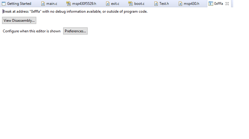
    Can you please suggest me where should I add this particular line. I was trying to add while after pin assigning and met with an issue. I have added screenshot of the issue below.

    If you have any example code for my setup, please share that for my information. That will be a great help for me.

    Regards

  • Hello,

    My apologies, that line of code is not needed on the device you're using, I've overlooked that.

    Here is some example code for the setup I2C from the TI Resource Explorer, however it uses USCI_B0 instead of B1 like in your code:

      P3SEL |= 0x03;                            // Assign I2C pins to USCI_B0
      UCB0CTL1 |= UCSWRST;                      // Enable SW reset
      UCB0CTL0 = UCMST + UCMODE_3 + UCSYNC;     // I2C Master, synchronous mode
      UCB0CTL1 = UCSSEL_2 + UCSWRST;            // Use SMCLK
      UCB0BR0 = 12;                             // fSCL = SMCLK/12 = ~100kHz
      UCB0BR1 = 0;
      UCB0I2CSA = 0x48;                         // Slave Address is 048h
      UCB0CTL1 &= ~UCSWRST;                     // Clear SW reset, resume operation
      UCB0IE |= UCRXIE;                         // Enable RX interrupt
      RXCompare = 0x0;

    You can find the rest of the code and other examples by following this link: 

    http://dev.ti.com/tirex/explore/node?node=APvjUT.Wo5XXtuhtROdtEw__IOGqZri__LATEST

    Is there a reason you chose to poll instead of using interrupts?

    Best,

    Colin Adema

  • Hello Dipin,

    Were you able to get your issue working?

  • Hello Dipin,

    We haven’t heard from you for a couple of days now, so I’m assuming you were able to resolve your issue.
    If this isn’t the case, please click the "This did NOT resolve my issue" button and reply to this thread with more information.
    If this thread locks, please click the "Ask a related question" button and in the new thread describe the current status of your issue and any additional details you may have to assist us in helping to solve your issues.

**Attention** This is a public forum