(I am reposting this because the first time I posted it selecting that the problem was in CCS. I am not sure if that is the case and if the former post would be visible to the public at large.)
I am facing a pretty weird situation. I am using a series of if-else loops inside a function to determine the signal going low at different GPIOs. On putting a breakpoint(or when executing in real time), two of those if loops are being entered even when the condition is clearly false. To give you an example,
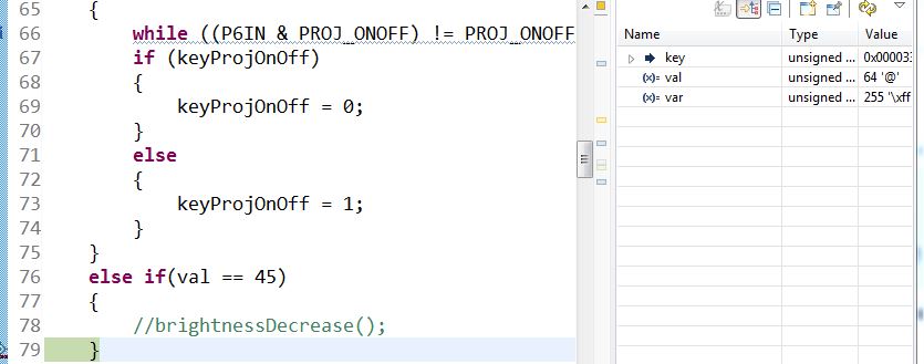
uint08 val = P6IN & 0x40; // value is 0x40 or 64. The input signal has been verified in the CRO as well. P6.6 is continously high
Case(i):
if(val == 45)
{
//The program flow enters here
}
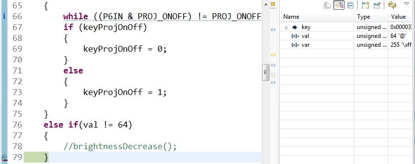
Case(ii):
if(val != 64)
{
//The program flow enters here
}
Please find the screenshots attached. I have tried various other ways of accomplishing the same, such as just doing if((P6IN & 0x40) != 0x40) but the behaviour doesn't change. Interestingly, the other if-else loops in the function are working fine.