This thread has been locked.

If you have a related question, please click the "Ask a related question" button in the top right corner. The newly created question will be automatically linked to this question.

MSP430F2272: JTAG Interface questions

Part Number: MSP430F2272
Other Parts Discussed in Thread: TIDA-020008, DRV8873
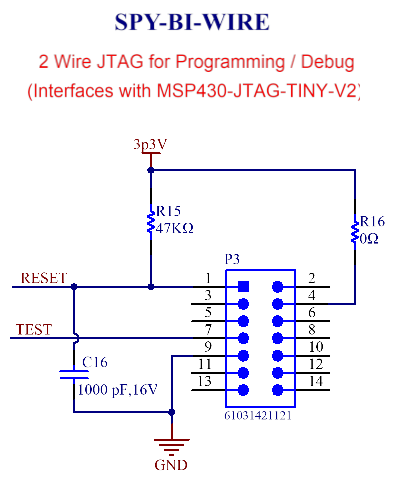
Since the MCU (MSP430F2272) uses a 2-Wire Spy-Bi-Wire (SBW) JTAG Interface for programming and debug,  it’s my understanding that the fundamental difference is that 2-wire devices implement additional logic that is used to convert the 2- wire communication into the standard 4-wire communication internally. Hence the communication between MCU (MSP430F2272) and the motor driver (DRV8873SPWPRQ1) occurs using 4 wire JTAG interface via TDI, TDO, TMS and TCK pins. Is this accurate?
Question I have is that the motor driver (DRV8873SPWPRQ1) JTAG interface is missing TCK i.e. it only show TDI, TDO, TMS and SCS pinouts, both of which are wired to the MCU (MSP430F2272). Since I was following TIDA-020008, I just want to make sure I’m not missing something. Kindly confirm.

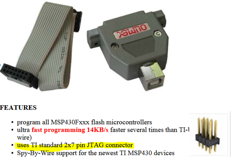
Also, what header should I use with MSP430-JTAG-TINY-V2?
Thanks
Viktorija

MSP430F2272

  • Hello Viktorija,

    Yes, you are correct about the SPY-BY-WIRE JTAG interface.  However, I'm a little confused though why you are asking about JTAG and the DRV8873?  This motor controller communicates with the MSP using a SPI interface, not JTAG.  You may be confusing the pin names since they are similar?  Refer to the MSP430x2xx family users guide for detailed information about the MSP430 SPI peripheral.

    Regarding the header for the MSP430-JTAG-TINY-V2, you need a 14pin (2x7), header with 0.1" spacing on the pins. (see photo below - note the header shown is a 2x4 just for reference)

  • Dennis, 

    From customer:

    Thanks a lot for the follow-up. Sorry I meant that MCU and the motor driver (DRV8873SPWPRQ1) occurs via SPI. But my question was that the motor driver is missing TCK pin? Has the TCK pin for the motor driver been replaced with SCS pin?

    I’ve added a 2x7 header (p/n 61031421121) which is 14 male pins header with pitch of 0.1” (2.54mm) and row spacing of 0.1” (2.54mm). My new Spy-By-Wire schematic is as follows. I hope this is Ok.


  • Hello Viktorija,

    Let me diagram the connections for you to make it easier to understand what's required to make this work.

    You need an MSP430 to control the DRV8873.  To program the MCU with your code all you need are RST and TEST (TST) pins on the MSP430.  Of course you will need +3.3v to power the MSP430.  The MSP430 controls the DRV8873 though the MSP430's SPI peripheral using SCLK, SDI and SDO.  There is an additional pin (usually a general purpose IO pin on the MSP430) that is used as a "chip select" for the motor controller.

    The TIDA-020008 is designed to interface to any of the MSP430 launchpads, but you mentioned the MSP430F2272.  Are you designing a PCB with MSP430F2272 and DRV8873 on same PCB?

    Based on the diagram below, does this answer your question?

  • Hi Dennis,

    Thanks for clarifying, the diagram is quite beneficial. Yes I've wired the chip select pin from motor driver to a general purpose pin (#33) of the MCU (MSP430F2272). So the MSP430's SPI peripheral to DRV8873 matches your diagram. 

    Yes the PCB design has both MSP430F2272 and DRV8873 on same PCB. I hope this is ok?

    Thanks,

    John

  • Hi John,

    Yes, you should be good to go.

    Make sure that you connect MSP430 MOSI -> DRV8873 SDI pin, and MSP430 MISO -> DRV8873 SDO pin

  • Hi Dennis,

    Thank you so much! I really appreciate your guidance.

    Best Regards,

    John

**Attention** This is a public forum