This thread has been locked.

If you have a related question, please click the "Ask a related question" button in the top right corner. The newly created question will be automatically linked to this question.

MSP430F5172: JTAG/SBW locking and unlocking; code example requested

Part Number: MSP430F5172
Other Parts Discussed in Thread: UNIFLASH, MSP-GANG, MSP-FET

I'm using CCS v9.3 as the IDE and the MSP430F5172 target.

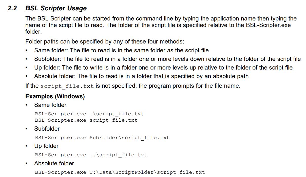
Simply, I wish to generate the .hex output file for upload using Uniflash in a production environment.  This .hex output file needs to be generated with C source code that will lock the JTAG/SBW interface as described in sla685 Section 2.2.1  I've already read sla685 and am still confused on how to do this operation.   Are there any code examples that show how this can be done? 

Specifically, I do not understand what this means:

"To program these addresses, the protected area of BSL flash must
first be unlocked by clearing the SYSBSLPE bit in the SYSBSLC register. After programming the
signatures, the BSL protection should be re-enabled."

How do I do the above in C code?

Then, if I need to unlock in order to re-flash the device, slau685 says:

"To clear JTAG/SBW lock protection, the BSL can be used to clear the JTAG signatures to 00000000h.
The BSL is password protected by the last 32 bytes of the interrupt vector table FFE0h–FFFFh (see
Section 4). Because the JTAG signature is located in the protected BSL area, the BSL must first clear the
SYSBSLPE bit in the SYSBSLC register (write 0003h to the address 0182h), before writing 00000000h to
the JTAG signatures."

What does this mean?  How do I "use" the BSL to clear SYSBSLPE?  How do I actually do any of this? 
I use the CCS IDE. I don't know how to, nor do I care to know what the BSL is and how to use it. 

Can somebody explain what I am missing here?

  • Hello,

    To lock the JTAG/SBW, you can enable "Make Device Secure" option in Uniflash.

    To unlock the JTAG/SBW  using BSL, please have a understanding of MSP430 Bootloader at MSPBSL. There are user's guide, bsl pc tool, hardware tool and some example which includes the unlock device example.

  • Any software / hardware BSL / SBW / JTAG should be able not only to flash target device, but also to change RAM contest, so BSL flash area protection on target device can be disabled by BSL interface. Fuse blow is simple, but reverse must include process for back-to-factory state (original BSL must be reflashed to restore fuse value to 0FFFFh). It is explained here...

    https://forum.43oh.com/topic/2972-sbw-msp430f550x-based-programmer/?do=findComment&comment=44019

    https://forum.43oh.com/topic/2972-sbw-msp430f550x-based-programmer/?do=findComment&comment=44140

  • OK This works. 
    Now, I have to figure out how to unlock JTAG/SBW
    Why is the unlock function not as simple?

  • I cannot follow these examples links you post above.  They are collections of posts from long ago with very old and outdated information about matters which do not concern me. 

    Can you please list out the steps I need to do in order to reflash the BSL onto the MSP430F5* series? 

    I do not understand the information in the links, they do not address what I am trying to do anyway, and I cannot find any guides, software or instructions on this entire forum on how to reflash the BSL to return the MSP440F5* to the factory state.

  • JTAG Fuse vale (factory default 0FFFFh)  is stored at the end of BSL segments (at address 017FCh). For JTAG fuse lock is enough flash write of 05555h double word (four 055h bytes). For JTAG fuse unlock is enough to 00000h flash write (overwrite 05555h with 00000h). But than device stays forever unlocked because flash value can be changed / restored back to 0FFFFh (factory default) only by segment erase first. So factory original BSL segment must be saved, erased, and written back. If something goes wrong during this sequence, device with fault BSL and blown JTAG  fuse is bricked. For BSL segment erase / read / write it should be unlocked first.

  • Everyone here is just repeating what the documentation already says, without providing any real life, workable solution with a series of steps to take in software and/or code. 

    "So original factory BSL segment must be saved, erased, and written back." 

    Ok .. so ...

    How do you save the original factory BSL?

    How do you erase the BSL?

    How do you write back the original factory BSL?

    Do you understand what I am asking?  You're just repeating what we've already read in the official TI documentation. TI's documentation on this is so lacking and convoluted I am amazed anybody except the experts at TI who write the bootloader are able to utiliize this information.   

    Pretend I am not a BSL expert.  Pretend I have not ever interacted with the BSL.  I use CCS and Uniflash only.    I do not know or understand about the BSL.  

    Please list the tools, setup, and steps I need to order to return the MSP430F51* back to the factory original state. 

    Anybody?   

  • (Maybe it exist somewhere, but) I didn't see till today open source C example that is solution for your request.

    BTW, I don't see what is point of repeatably locking / unlocking JTAG fuse, because firmware update can be done by BSL too, and as I can see (from your first topic post), in any case firmware (.hex file) is unprotected.

  • Yes, I think you have lost in mass information. But I have gave the useful resources link MSPBSL, which includes tools, setup, steps. Since the BSL is not in few words, you still need few hours to learn how to use them.  I summary the key steps you need to do:

    1. For software tool, you need download  BSL-SCRIPTER, which is a command line application that performs the commands or script to flash device.

    2. For hardware tool, one of the MSP-FET, MSP-GANG and MSPBSL_Rocket_FW is OK. The F5172 supoorts BSL through UART communication. It means you need make a connections between F5172 and MSP-FET or other tools as below. 

    For F5172, it should be P3.7 as TXD, P3.6 as RXD for 40-pin package. Please get actual TXD/RXD from below table for different packages.

    3. After downloading the BSL Scripter, and making correct connections, you need run the BSL Scripter with a unlock device example script. To run the application, please follow below example.

    There are some script examples within BSL Scripter download, including JTAG unlock example.


  • For F5172, it should be P3.7 as TXD, P3.6 as RXD for 40-pin package. Please get actual TXD/RXD from below table for different packages.

**Attention** This is a public forum