


Tool/software: Code Composer Studio
Hello,
I am using the MSP430F6638 mcu and I wanted to test the ADC12. I've written some code to do it and I have in my code a ADC12_ISR. I have put a breakpoint inside the ISR in order to know if the code enter inside it which will mean that a conversion is completed. Unfortunately the program never enter the ADC12_ISR and so I can't test the ADC. So I tried to find out what's the problem and I started by checking if the SMCLK which sources the ADC12CLK has the right frequency. MSP430F6638 has a pin that can be configured to be uses as SMCLK (Pin 3.4). So I configured this pin in order to select the SMLCK function and test if I have the right frequency. In my design I have two external crystals : a 32,768 kHz crystal for XT1 and a 8 MHz crystal for XT2. I have configured UCSCTL4 register so ACLK is sourced from XT1 and SMCLK from XT2. So after I have executed the code, I have noticed that I don't have a 8 MHz clock signal on P3.4 at all. Here is a picture of the result on the oscilloscope.
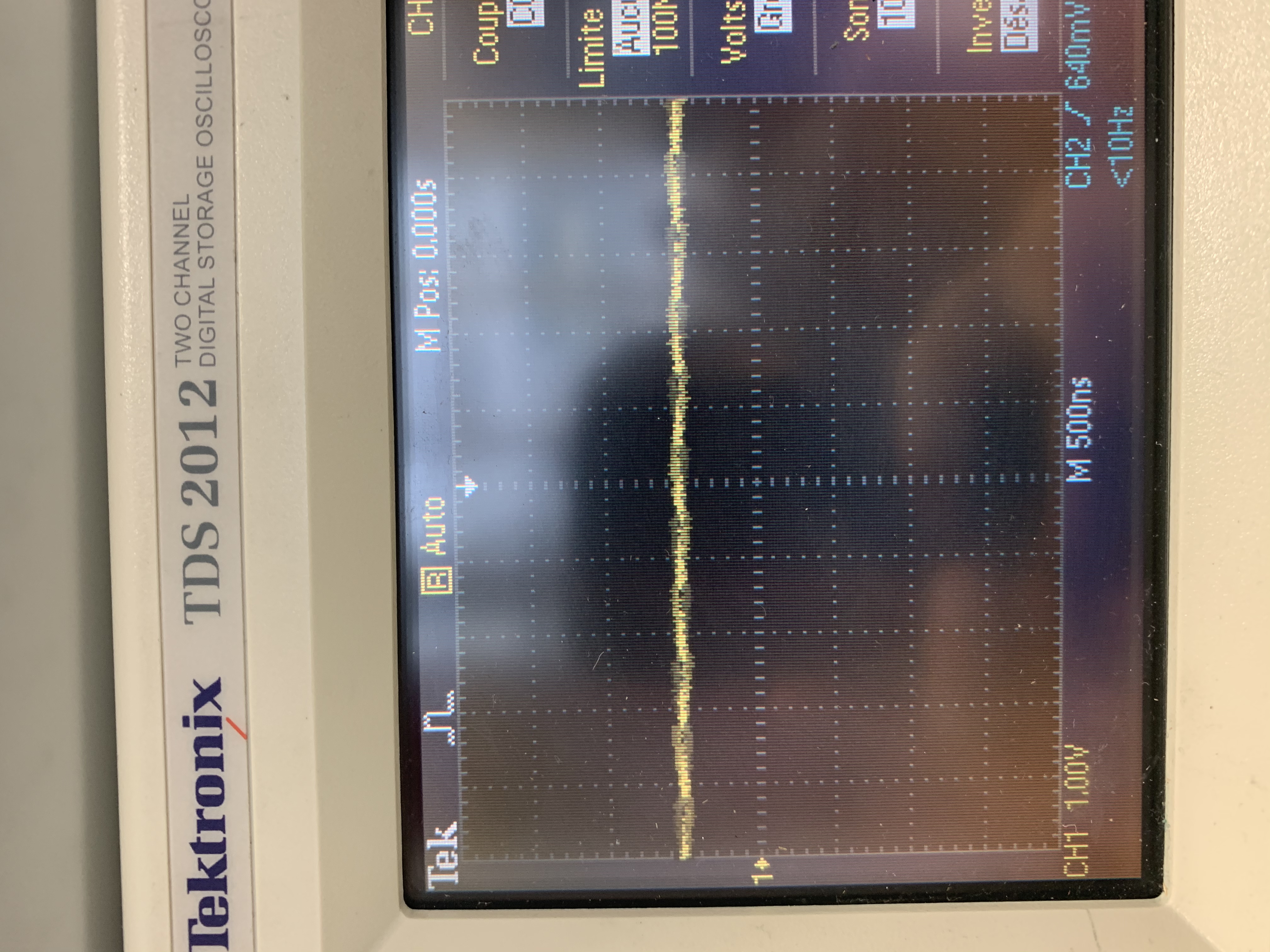
The MCU has a 3.3 V power supply and here I only have 1 V of amplitude and absolutely not a frequency of 8 MHz. The datasheet of 8 MHz crystal say that the load capacitance is 18 pF. I have used 33 pF external caps since formula (3) of http://www.ti.com/lit/an/slaa322d/slaa322d.pdf says Cload = (CL1 + Cparasitic)/2 = (33 pF + 2 pF)/2 = 17.5 pF which very close to 18 pF. I really don't understand this result. Here is my code :
int main(void)
{
WDTCTL = WDTPW | WDTHOLD; // stop watchdog timer
_BIS_SR(GIE);
UCSCTL4|=SELA__XT1CLK|SELS__XT2CLK; // source ACLK from XT1 and SMCLK from XT2
UCSCTL6&=~XT2DRIVE_3; // 00b so a range of 4 to 8 MHz since the external crystal on XT2 is 8 MHz
UCSCTL6|=XCAP_0; // 1pF internal cap
UCSCTL6&=~XT2OFF; // turn on XT2
UCSCTL6&=~XT1OFF; // turn on XT1
P3SEL|= BIT4; // Select SMCLK function of P3.4
P3DIR|= BIT4; // Configured as output
}
Also here in the program I don't see any mistake mainly that I have checked in the registers if there is the right values while debugging. Could someone help ? I really don't have any idea what's wrong and if there is a mistake.
Thank you,
Regards,
Mike

