This thread has been locked.

If you have a related question, please click the "Ask a related question" button in the top right corner. The newly created question will be automatically linked to this question.

MSP430F2619S-HT: Possible to manually calibrate Segment A? New MCUs don't have Segment A

Part Number: MSP430F2619S-HT
Other Parts Discussed in Thread: MSP430F2619, UNIFLASH, MSP-FET

Hello,

I have some new MSP430F2619 microcontrollers.  So far, each one has had a blank Segment A, which is used for clock timing.  As I understand it, the MCUs are calibrated at the factory so the clocks are accurate over their specified temperature range, and this calibration information is stored in Segment A.

I have some Segment A calibration coefficients from other chips, and I've tried loading those on to these new ones.  Some work, some don't, but there isn't a way to know if those other coefficients would work over the whole temperature range.

Is there a way to manually calibrate these chips?

  • If you have a 32kHz clock source (crystal, e.g.), Example msp430x261x_dco_flashcal.c will reconstruct the (4x) DCO constants in InfoA.

    http://dev.ti.com/tirex/explore/node?node=AJONAwnL3yWdDoTGcuFCOw__IOGqZri__LATEST

    I also found that transplanting those constants between chips worked poorly.

  • Hi Bruce,

    Thank you for contribution to E2E community.

    As I know in FRAM device, the clock timing is calibrated  when it is still a die and not packaged. After package, because of pressure, the parameter is not correct, which is over spec compared with the datasheet. We are planning to write a new Errata.

    I am not sure if it same reason on flash. If you can provide more details. I can check it.

    Eason

  • Hi Eason,

    The parts we are using is MSP430F2619SKGD1 , we get those die from Micross and Semi Dice. Both do not come with Segment A recently.

    Could you please confirm is there a process changed, the calibration is done on packaged not a die? 

    Thanks,

    Peng

  • When we worked with the F2619 in KGD, they came with the DCO constants in InfoA. But that was 10 years ago.

  • Hi Peng,

    normally the DCO calibration data were programmed during TI production test and will be verified functional and parametric al during final test.

    Can you please check if the Good Die Records stored in info memory segment D are valid? Maybe please post a memory dump of the whole info memory of an affected unit.

    Also please share the top site markings of the affected devices.

    Besides this some question to the handling on your site:

    1. Where the affected parts fresh from a reel?

    2. Did you ever programmed your own code or did you experienced missing DCO cal data right from the beginning?

    3. Which tools are you using (SW and HW) to access the devices?

  • Hi Peng Li,

    The part number you can see on the chip is just include the device number(MSP430F2619), TI icon, die version and the track number. What do you mean by"SKGD1" , it seems like a track number.

    According to our datasheet, the segment A should have calibrate data and it has write and erase protection. Normally, this problem should not happen. How many chips have this problem? Have you connect with Micross and Semi Dice?

    Yes, you can manually trim the clock, but it is not easy, especially for large amount of device. You need a accuracy clock source and control the registers to change the internal resistor and capacitor. The clock calibration data is different for different device. 

    Eason

  • Hi Peng,

    Here is the code example for you to re-calibrate manually.

    msp430x22x4_dco_flashcal.c
    /* --COPYRIGHT--,BSD_EX
     * Copyright (c) 2012, Texas Instruments Incorporated
     * All rights reserved.
     *
     * Redistribution and use in source and binary forms, with or without
     * modification, are permitted provided that the following conditions
     * are met:
     *
     * *  Redistributions of source code must retain the above copyright
     *    notice, this list of conditions and the following disclaimer.
     *
     * *  Redistributions in binary form must reproduce the above copyright
     *    notice, this list of conditions and the following disclaimer in the
     *    documentation and/or other materials provided with the distribution.
     *
     * *  Neither the name of Texas Instruments Incorporated nor the names of
     *    its contributors may be used to endorse or promote products derived
     *    from this software without specific prior written permission.
     *
     * THIS SOFTWARE IS PROVIDED BY THE COPYRIGHT HOLDERS AND CONTRIBUTORS "AS IS"
     * AND ANY EXPRESS OR IMPLIED WARRANTIES, INCLUDING, BUT NOT LIMITED TO,
     * THE IMPLIED WARRANTIES OF MERCHANTABILITY AND FITNESS FOR A PARTICULAR
     * PURPOSE ARE DISCLAIMED. IN NO EVENT SHALL THE COPYRIGHT OWNER OR
     * CONTRIBUTORS BE LIABLE FOR ANY DIRECT, INDIRECT, INCIDENTAL, SPECIAL,
     * EXEMPLARY, OR CONSEQUENTIAL DAMAGES (INCLUDING, BUT NOT LIMITED TO,
     * PROCUREMENT OF SUBSTITUTE GOODS OR SERVICES; LOSS OF USE, DATA, OR PROFITS;
     * OR BUSINESS INTERRUPTION) HOWEVER CAUSED AND ON ANY THEORY OF LIABILITY,
     * WHETHER IN CONTRACT, STRICT LIABILITY, OR TORT (INCLUDING NEGLIGENCE OR
     * OTHERWISE) ARISING IN ANY WAY OUT OF THE USE OF THIS SOFTWARE,
     * EVEN IF ADVISED OF THE POSSIBILITY OF SUCH DAMAGE.
     *
     *******************************************************************************
     * 
     *                       MSP430 CODE EXAMPLE DISCLAIMER
     *
     * MSP430 code examples are self-contained low-level programs that typically
     * demonstrate a single peripheral function or device feature in a highly
     * concise manner. For this the code may rely on the device's power-on default
     * register values and settings such as the clock configuration and care must
     * be taken when combining code from several examples to avoid potential side
     * effects. Also see www.ti.com/grace for a GUI- and www.ti.com/msp430ware
     * for an API functional library-approach to peripheral configuration.
     *
     * --/COPYRIGHT--*/
    //******************************************************************************
    //  MSP430F22x4 Demo - DCO Calibration Constants Programmer
    //
    //  NOTE: THIS CODE REPLACES THE TI FACTORY-PROGRAMMED DCO CALIBRATION
    //  CONSTANTS LOCATED IN INFOA WITH NEW VALUES. USE ONLY IF THE ORIGINAL
    //  CONSTANTS ACCIDENTALLY GOT CORRUPTED OR ERASED.
    //
    //  Description: This code re-programs the F2xx DCO calibration constants.
    //  A software FLL mechanism is used to set the DCO based on an external
    //  32kHz reference clock. After each calibration, the values from the
    //  clock system are read out and stored in a temporary variable. The final
    //  frequency the DCO is set to is 1MHz, and this frequency is also used
    //  during Flash programming of the constants. The program end is indicated
    //  by the blinking LED.
    //  ACLK = LFXT1/8 = 32768/8, MCLK = SMCLK = target DCO
    //  //* External watch crystal installed on XIN XOUT is required for ACLK *//
    //
    //           MSP430F22x4
    //         ---------------
    //     /|\|            XIN|-
    //      | |               | 32kHz
    //      --|RST        XOUT|-
    //        |               |
    //        |           P1.0|--> LED
    //        |           P2.1|--> SMLCK = target DCO
    //
    //  A. Dannenberg
    //  Texas Instruments Inc.
    //  April 2006
    //  Built with CCE Version: 3.2.0 and IAR Embedded Workbench Version: 3.41A
    //******************************************************************************
    #include <msp430.h>
    
    #define DELTA_1MHZ    244                   // 244 x 4096Hz = 999.4Hz
    #define DELTA_8MHZ    1953                  // 1953 x 4096Hz = 7.99MHz
    #define DELTA_12MHZ   2930                  // 2930 x 4096Hz = 12.00MHz
    #define DELTA_16MHZ   3906                  // 3906 x 4096Hz = 15.99MHz
    
    unsigned char CAL_DATA[8];                  // Temp. storage for constants
    volatile unsigned int i;
    int j;
    char *Flash_ptrA;                           // Segment A pointer
    void Set_DCO(unsigned int Delta);
    
    int main(void)
    {
      WDTCTL = WDTPW + WDTHOLD;                 // Stop WDT
      for (i = 0; i < 0xfffe; i++);             // Delay for XTAL stabilization
      P1OUT = 0x00;                             // Clear P1 output latches
      P1DIR = 0x01;                             // P1.0 output
      P2SEL |= 0x02;                            // P2.1 SMCLK output
      P2DIR |= 0x02;                            // P2.1 output
    
      j = 0;                                    // Reset pointer
    
      Set_DCO(DELTA_16MHZ);                     // Set DCO and obtain constants
      CAL_DATA[j++] = DCOCTL;
      CAL_DATA[j++] = BCSCTL1;
    
      Set_DCO(DELTA_12MHZ);                     // Set DCO and obtain constants
      CAL_DATA[j++] = DCOCTL;
      CAL_DATA[j++] = BCSCTL1;
    
      Set_DCO(DELTA_8MHZ);                      // Set DCO and obtain constants
      CAL_DATA[j++] = DCOCTL;
      CAL_DATA[j++] = BCSCTL1;
    
      Set_DCO(DELTA_1MHZ);                      // Set DCO and obtain constants
      CAL_DATA[j++] = DCOCTL;
      CAL_DATA[j++] = BCSCTL1;
    
      Flash_ptrA = (char *)0x10C0;              // Point to beginning of seg A
      FCTL2 = FWKEY + FSSEL0 + FN1;             // MCLK/3 for Flash Timing Generator
      FCTL1 = FWKEY + ERASE;                    // Set Erase bit
      FCTL3 = FWKEY + LOCKA;                    // Clear LOCK & LOCKA bits
      *Flash_ptrA = 0x00;                       // Dummy write to erase Flash seg A
      FCTL1 = FWKEY + WRT;                      // Set WRT bit for write operation
      Flash_ptrA = (char *)0x10F8;              // Point to beginning of cal consts
      for (j = 0; j < 8; j++)
        *Flash_ptrA++ = CAL_DATA[j];            // re-flash DCO calibration data
      FCTL1 = FWKEY;                            // Clear WRT bit
      FCTL3 = FWKEY + LOCKA + LOCK;             // Set LOCK & LOCKA bit
    
      while (1)
      {
        P1OUT ^= 0x01;                          // Toggle LED
        for (i = 0; i < 0x4000; i++);           // SW Delay
      }
    }
    
    void Set_DCO(unsigned int Delta)            // Set DCO to selected frequency
    {
      unsigned int Compare, Oldcapture = 0;
    
      BCSCTL1 |= DIVA_3;                        // ACLK = LFXT1CLK/8
      TACCTL2 = CM_1 + CCIS_1 + CAP;            // CAP, ACLK
      TACTL = TASSEL_2 + MC_2 + TACLR;          // SMCLK, cont-mode, clear
    
      while (1)
      {
        while (!(CCIFG & TACCTL2));             // Wait until capture occured
        TACCTL2 &= ~CCIFG;                      // Capture occured, clear flag
        Compare = TACCR2;                       // Get current captured SMCLK
        Compare = Compare - Oldcapture;         // SMCLK difference
        Oldcapture = TACCR2;                    // Save current captured SMCLK
    
        if (Delta == Compare)
          break;                                // If equal, leave "while(1)"
        else if (Delta < Compare)
        {
          DCOCTL--;                             // DCO is too fast, slow it down
          if (DCOCTL == 0xFF)                   // Did DCO roll under?
            if (BCSCTL1 & 0x0f)
              BCSCTL1--;                        // Select lower RSEL
        }
        else
        {
          DCOCTL++;                             // DCO is too slow, speed it up
          if (DCOCTL == 0x00)                   // Did DCO roll over?
            if ((BCSCTL1 & 0x0f) != 0x0f)
              BCSCTL1++;                        // Sel higher RSEL
        }
      }
      TACCTL2 = 0;                              // Stop TACCR2
      TACTL = 0;                                // Stop Timer_A
      BCSCTL1 &= ~DIVA_3;                       // ACLK = LFXT1CLK
    }
    

    Eason

  • Dietmar,

    Thanks for the response.  There is nothing in the information segments contained in memory range 0x1000 to 0x10FF.  

    We order these MCUs as bare dies, so I can't check the top markings at the moment.  But I'll get that info later.

    1.  Parts arrive as bare dies in a waffle pack.

    2. Missing cal data right from the beginning.  The memory dump I provided was pulled from a new MCU that we just barely bonded to our circuit and had not been programmed yet.

    3. For this one, I used a TI MSP-FET Flash Emulation Tool to access the memory via JTAG.  I first used UniFlash to read the memory, but it doesn't export the memory dump in nice format so I used FET-Pro430 to export the file I attached to this post

    Thanks!

    MSP430F2619S-HT_no_info_seg.txt

  • Hi Eason,

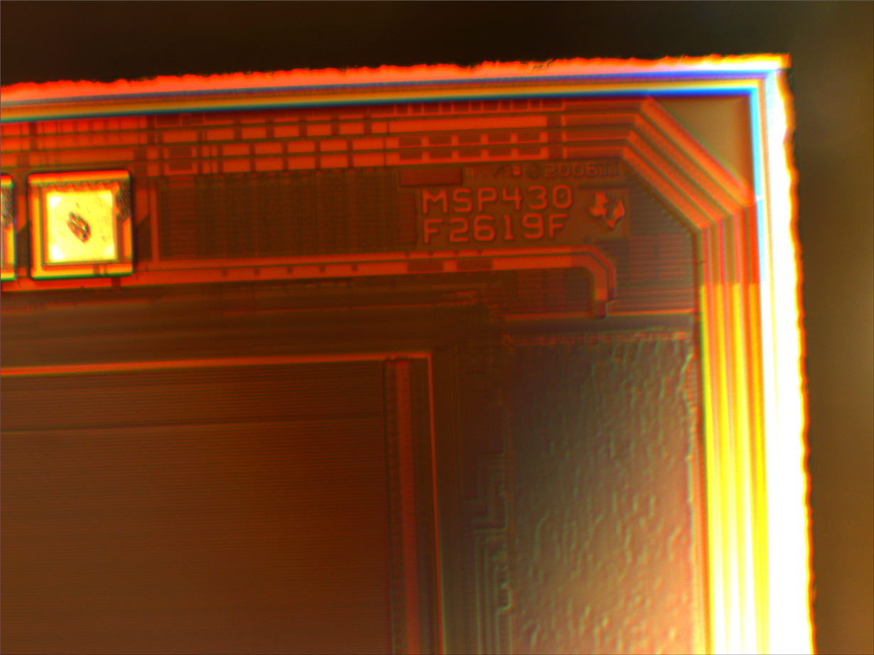
    We purchased those bare dies last month and tested about 10 bare die and all show blank Segment A recently. Please see attachment for die making. The distributors direct us to TI to get more info.

    The MSP430F2619F die we received 5 years ago all came with Segment A. So I am wondering anything changed on TI's side.

    Thanks,

    Peng

  • Hi Peng,

    the content of the memory looked really strange, normally there are good die record information in info mem segD which are missing here. Also the info and main memory show bits which a programmed to ZERO. Normally the devices are delivered fully erased.

    Bare DIE makes back tracing a bit more complicated here. So we would require details on shipping to trace back where the material came from we will contact you offline on this.

  • Peng, Todd,

    did you receive my email? Can you please provide the shipping details via mail so that we can trace back the material?

**Attention** This is a public forum