Tool/software: Code Composer Studio
I am trying to count pulses with MSP-EXP430FR5969 from external source at switch P1.1 . i config timer TA0 to capture the pulses and enable global interrupts.
TIMER0_A3 interrupt vector service routine used for counting pulses. i set breakpoints in order to debugging at interrupt routine lines
the code jump to interrupt services as pressing switch (P1.1 is triggered) and then it continued triggering without pressing switch !!!
the StoredCount increasing!
I would really appreciate it if you could solve my problem
#include "driverlib.h"
void initGPIO(void);
void initClocks(void);
#define NUMBER_TIMER_CAPTURES 20
volatile unsigned int StoredCount = 0;
int main(void) {
WDT_A_hold(WDT_A_BASE);
initClocks();
initGPIO();
// TA0CCTL2, Capture/Compare Control Register 0 for TA0
TA0CCTL2 |= CCIE; // interrupt enable
TA0CCTL2 |= CCIS_0; // capture off of CCI0A //The capture inputs CCIxA are connected to external pins selected with the CCIS bits.
TA0CCTL2 |= CM_2; // capture on falling edge
TA0CCTL2 |= CAP; // capture mode
//Timer_A0 Control Register
TA0CTL |= TASSEL_2 ; // source timer A1 from SMCLK
// TA0CTL |= MC1;//// Start timer
TA0CTL |=TACLR;
//TA0CTL |=TAIE;
_BIS_SR(GIE);
__no_operation();
// while(1)
// {
// }
}
void initClocks(void)
{
/* Clock System Setup, MCLK = SMCLK = DCO (1MHz), ACLK = VLOCLK */
CSCTL0_H = CSKEY >> 8;
CSCTL1 = DCOFSEL_0;
CSCTL2 = SELA__VLOCLK | SELS__DCOCLK | SELM__DCOCLK;
CSCTL3 = DIVA__1 | DIVS__1 | DIVM__1;
CSCTL0_H = 0;
}
void initGPIO(void)
{
/* Configure GPIO to default state */
P1OUT = 0; P1DIR = 0xFF;
P2OUT = 0; P2DIR = 0xFF;
P3OUT = 0; P3DIR = 0xFF;
P4OUT = 0; P4DIR = 0xFF;
PJOUT = 0; PJDIR = 0xFFFF;
GPIO_setAsOutputPin(GPIO_PORT_P4, GPIO_PIN6); // Set P4.6 to output direction
GPIO_setAsOutputPin(GPIO_PORT_P1, GPIO_PIN0); // Set P1.0 to output direction
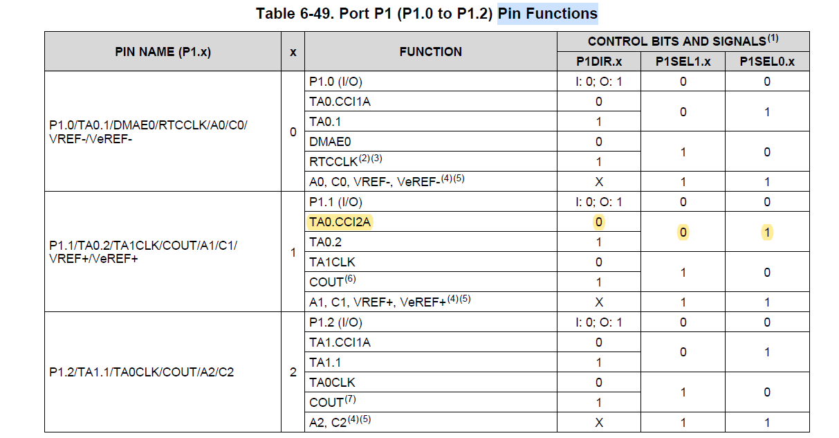
GPIO_setAsInputPinWithPullUpResistor(GPIO_PORT_P1,GPIO_PIN1);//pull up P1.1 //P1DIR &= ~BIT4; P1SEL1 &= ~BIT4; P1SEL0 |= BIT4;
GPIO_setAsPeripheralModuleFunctionInputPin(GPIO_PORT_P1, GPIO_PIN1,GPIO_SECONDARY_MODULE_FUNCTION);//P1.1 is used as input capture setup pin 1.1/TA0.CCI2A
// setup pin 1.1/TA0.CCI2A
// P1DIR &= ~BIT1;
// P1SEL1 &= ~BIT1;
// P1SEL0 |= BIT1;
/* Disable the GPIO power-on default high-impedance mode. */
// PM5CTL0 &= ~LOCKLPM5; Lock bit is cleared:
PMM_unlockLPM5();
}
#pragma vector = TIMER0_A1_VECTOR
__interrupt void Timer0_A1_ISR (void)
{
StoredCount ++;
}