This thread has been locked.

If you have a related question, please click the "Ask a related question" button in the top right corner. The newly created question will be automatically linked to this question.

MSP430F437: Reed Switch Control Solution

Part Number: MSP430F437
Other Parts Discussed in Thread: CC2650, TIDM-BLE-REEDMTR,

Hello MSP Team,

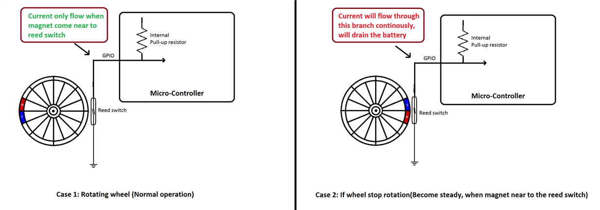
Need your inputs on this. Our customer is into a battery-operated flow measurement application using a meter. This meter has a magnet attached to a wheel, which is then detected by the system using a reed switch. However, they're having issues when the meter wheel magnet asserts the reed switch; it remains on this condition leading to the GPIO being pulled low and causing increased current consumption even at sleep mode.

We've tried proposing TIDM-BLE-REEDMTR as solution - utilizing the sensor controller engine of CC2650 for the interrupts. However, they're quite restricted in using MSP430F437 for this application.

Can you advise on any hardware/software solution for implementing this in MSP430F437?

In case you need more information, please let me know. Thank you for your support.


Kind Regards,

Jejomar


  • I assume this is if the read switch happens to have the magnet near the switch when the flow stops.

    Assuming they are using an interrupt to trigger the flow count, use the interrupt to put the GPIO in a high impedance state and use a timer to periodically check the state. Once it goes high, release the timer and continue as normal.

    Use a monostable multivibrator to send a short pulse on the high to low transition.

  • Sounds like there is a pull-up on the reed switch and then the switch is held closed to ground, completing the circuit.  

    Is the current even coming from the MSP430 or just from the pull-up on the reed switch being held closed?  Are they using the internal pull-up in the MSP430 or external?  

    If they are using the internal pull-up they could do something in software like what Keith suggests.  Disable it but go to a polling routine.  It could cause issues at high flow rates so they may have to balance the wake-up timing.

    Thanks,

    JD   

  • Thanks for purposed suggestions. We need more clarification in simple terms so we can understand it well.

    We are again providing our case issue details here, so you can understand our issue well.

    Dear, We are facing an issue, in normal mode our system consumes 1.5uA of current, but in a special case system consumes about 550uA-600uA in sleep mode.

    System Description:
    We use MSP430F437IPNR MCU for our application and it is battery operated ultra low power consumption system.System remains most of time in sleep mode. We use this system to measure the consumption of fluid flowing by a meter. This meter has a magnet attach to a wheel, which is detected by our system using a reed switch. this reed switch wakes the system and a variable counter incremented and store in EEPROM for further process when MCU is in active mode. We currently use internal pull up configuration. but we can use any configuration, pull-up or pull-down of resistor.

    Issue description:
    our system consumes about 1.5uA in sleep mode. that's perfect for our application. But there is an issue here. When meter wheel magnet reached at our reed switch position and remains there(this happens mostly times), then reed switch remains detected(GPIO detects low) till no other fluid flow through meter. In that case also, system is in sleep mode, but current consumption increased to 550uA-600uA .

    According to our analysis, as our system is internally pulled up of 60kΩ and reed switch provide ground when detect magnetic filed, so circuit completed and current flows from it, till reed switch release by flowing fluid through meter. So, whenever reed switch detects , there will always 550uA-600uA current consumes in system. if reed switch remains detected then 550-600uA continuously flows from battery, which is not affordable to us as our system runs on battery.

    Please help us to find the solution for it, is there any mechanism of MCU we can use or any other external component or IC can be used in our application. Please find a simple representation of our system in attachment(this is only for representation).

    Thank You

  • Use an external pullup of 1 M or greater - as high as you can get away with. Turn off the internal pull up.

    use my idea above, and turn off the pull-up as soon as the switch closes. periodically turn the pull-up on and see if the magnet has moved, once it does turn on the pullup and continue as normal. The advantage of this is that it is software only.

    Capacitively couple the signal to the MCU so that you only get pulses.

  • I think you can scrap the capacitively coupled idea, a quick test of SPICE could not get it to work.

    In any case there appears to be another issue here. A 60K resistor with a 3.3 v source should draw 55 uA, not 600 uA. There must be some other resistance in the circuit, or your software keeps the system in active mode whenever the switch is closed.

    This goes back to my idea of a monostable multivibrator which will output a pulse every time it detects the switch closing.

  • Thanks Dear for suggestion,

    We would like to know if we use external 1M resistor, then there may be high noise. The wire length of reed switch is about 3 meter and with 1M resistor, it can generate more noise and may give false triggers.

    Any solution for this?

    Thank You

  • Probably not, but you can use a capacitor to filter any noise. How much noise do you have now? A 1M will be about 10x worse.

  • Dear,
    Please provide your suggestion regrading, what are the chances of getting false trigger if we use 1M pull-up Resistor ?

    Thank You

  • Since I have no idea what kind of noise levels you may have in your system, I am not able to guess.

  • Hey Dipu,

    I agree with Keith that there are 2 main options here. 

    1. Implement a larger external pull-up to lower the current when in this state. 
    2. Implement some software routine to somehow detect this state and detect when you leave this state.  (would probably require the use of a timer for periodic wake-ups while the reed switch is closed.) 

    I think you will have to test these implementations in your system and see what will work best for you.   

    Thanks,

    JD 

  • A simple solution might be to put a capacitor in series between the reed switch and the iopin/pullup.  When the reed switch shorts to ground, this will pull the input low until the capacitor charges through the pull up resistor.  Detect the falling edge and voila' you have it.  Pick the capacitor/pull up resistor combination so that the time constant is faster than the fastest rotational speed you expect.

  • Already suggested. 8^) Have you tried this? I tried a mock-up in SPICE and could not get it to  work.

  • I have used this before.  You might try lowering the pull up value.  It is easy to breadboard. I don't always trust simulations. You might try putting a resistor I'm parallel with the cap that is 5 to 10 times bigger than your pull up value.

**Attention** This is a public forum