This thread has been locked.

If you have a related question, please click the "Ask a related question" button in the top right corner. The newly created question will be automatically linked to this question.

MSP430F449: Linearity of Processor frequency f(System) to Supply Voltage

Part Number: MSP430F449

Hello,

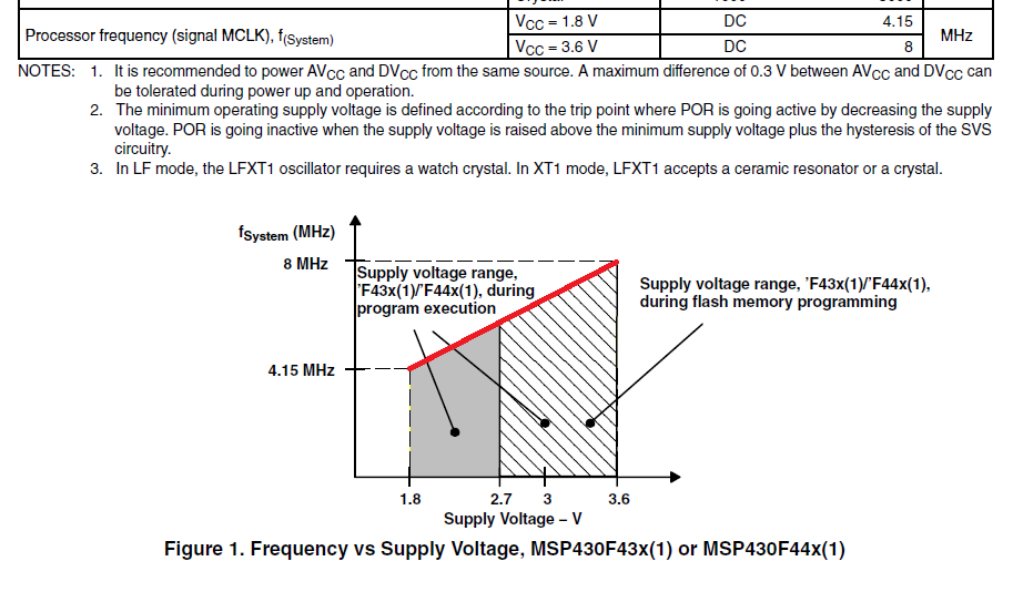
The DS page-37 tells the recommended operating condition for Processor frequency (signal MCLK) f(System). There are a table and the Figure 1.

The Figure 1 has a line between the two points:

(Supply Voltage, fSystem ) = (1.8V, 4.15MHz) and (3.6V, 8MHz).


Then, is it possible to expect the line between the two points are Linear or not ?

As the background, my customer asked me if the CPU works at 8MHz under Vcc=3.3V. We would like to decide the CPU clock frequency under the supply voltage which is not specified.


  • Hello,

    many thanks for contacting us on this topic. Yes, the characteristic can be assumed as linear.

    This means, translating the graph into a slope of the characteristic results in 2.138MHz/V slope. This means e.g. at 2.7V the specified maximum operating frequency would be fmax(2.7V) = 8MHz - (0.9V * 2.138MHz/V) = 6.075MHz.

    A few additional comments:

    I case your customer would like to operate the device from a high frequency crystal or ceramic resonator, please keep in mind the frequency specification does not include only the frequency as critical parameter, but also the minimum pulse width applied to the CPU or module clocks. The minimum pulse width can be derived from the frequency value assuming a 50/50 duty cycle. There is some margin in the values from our side, to allow e.g. also the operation from the integrated FLL/DCO, which is running a modulated clock. Still, if for some reasons the oscillator signal derived from a crystal or a resonator would be subject to extensive duty cycle shift, this would potentially overclock the CPU and/or modules. A duty cycle shift could occur on startup of the crystal oscillator, or from electromagnetic or mechanical disturbances. To prevent this risk, the crystal oscillator clock should not be used with a divider setting 1, but 1/2, in case of harsh operating conditions of the application. Another and anyway recommended approach in terms of EMI, is of course a robust and best practice HW design, to mitigate these potential effects, when using the clock with 1/1 divider.

    Best regards

    Peter

  • Peter,

    Thank you very much. Very clear.

**Attention** This is a public forum