


I am trying to first just establish I2C communication between an MSP430F169 and an SI514-PROG-EVB. This is how I have it connected:

And this is the output on the logic analyzer:
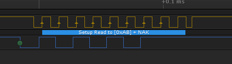
That is the problem, it always gives NAK, I can't get it to ACK.
Here is the sentence from the SI-514-PROG-EVB that explains how to make the I2C connection, to check that it matches the way I drew it (and connected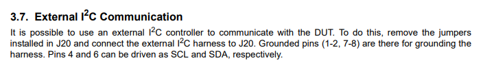
Also, when I have the MSP430 not connected to the SI514 at all, I get the exact same output on the logic analyzer (shown above). But when I have the MSP430 connected to the SI514, but I remove the USB power from the SI514, I get this on the logic analyzer:

Lastly, here is my code. It is mostly from some examples. The slave address is correct:
int main(void)
{
WDTCTL = WDTPW + WDTHOLD;
P3SEL |= 0x0A; // Set P3.3 to SCL and P3.1 to SDA
U0CTL |= I2C + SYNC; // Switch USART0 to I2C mode
U0CTL &= ~I2CEN; // Recommended I2C init procedure
I2CTCTL = I2CSSEL_2; // SMCLK
I2CSCLH = 0x03; // High period of SCL
I2CSCLL = 0x03; // Low period of SCL
I2CNDAT = 0x01; // Transmit one byte
I2CSA = 0x55; // Slave address
U0CTL |= I2CEN; // Enable I2C, 7 bit addr,
while(1)
{
U0CTL |= MST;
I2CTCTL |= I2CSTT + I2CSTP;
__no_operation();
}
}


