This thread has been locked.

If you have a related question, please click the "Ask a related question" button in the top right corner. The newly created question will be automatically linked to this question.

MSP430F447: MSP430x44x Vs ADC THS1206 Interface

Part Number: MSP430F447
Other Parts Discussed in Thread: THS1206, TMS320C6201, , ADS8342, TM4C123FH6PM

Hello,

I received the MCU MSP430 Vs ADC THS1206 EVM source code from the ADC forum at the address below.

https://e2e.ti.com/support/data-converters/f/73/p/911632/3390319#3390319

/cfs-file/__key/communityserver-discussions-components-files/73/THS1206.zip

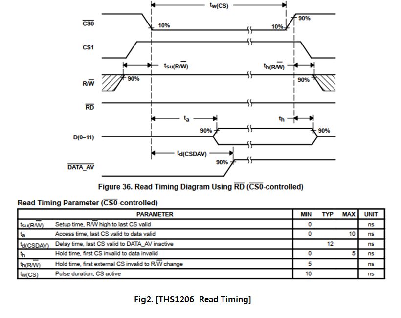
I am not sure how to make Read Timing like Fig2 using MSP430x44x GPIO mode.

Q1> How to make tw(CS), tsu(R/nW), th(R/nW) of /CS0 & CS1 signals by taking one of several signals as an example?

     Could you please tell me where the source code is located at the address above?

Best Regards,
Jame, Shin

  • Hello Ti Engineer,

    There is a file THS1206.c in the ZIP file of the link address of the previous post.

    Q2> Please explain if read_adc(void) function makes Tw(CS) = min 10ns timing. ?

    Best Regards,
    Jame, Shin

    /****************************************************************/
    /* FILENAME: main.c                            		        */
    /* DESCRIPTION: This program uses the MSP430F449 to read 500 	*/
    /*    samples from the ADS8342 16-bit 250KSPS Parallel ADC.     */  
    /*    The samples are stored in the buffer adc_data.            */
    /*    Refer to the .map file created by the compiler for the    */  
    /*    address in memory for adc_data.  Data is then transferred */
    /*    to buffer dac_data and sent a DAC7731.  The LCD displays  */
    /*    which direction data is traveling.                        */
    /*    AUTHOR: Tom Hendrick, Data Acquisition Products,          */  
    /*            Dallas Texas                                      */
    /*    CREATED 2003(C) BY TEXAS INSTRUMENTS INCORPORATED.  	*/
    /*    VERSION: 1.0 						*/
    /****************************************************************/
    #include <msp430x44x.h>
    #include "SBLCDA2.h"
    #include "THS1206.h"
    
    /**************** Function prototypes ***********************************/
    /*                                                                      */
    void init_sys(void);                /* MSP430 Initialisation routine    */
    void delay(int);                   /* Software delay                   */
    void adc_read(void);             /* Do the adc conversion            */
    void display(void);                 /* Indicate Program complete        */
    void complete(void);
    void timer(void);
    void InitializeLCD( void );
    void clearDisplay( void );
    void sortMajor( unsigned int );
    void displaySpecial( long int );
    void displayMinor( int, int );
    void displayHPA449(void);
    
    void reset_adc(void);
    void config_adc(void);
    /*                                                                      */            
    /************************************************************************/
    
    /************************************************************************/
    /*                                                                      */
    /* Global variable declarations                                         */
    /*                                                                      */
    /************************************************************************/
    
    unsigned int    adc_data[4];        // Storage for converted data
    unsigned int    hi_byte, lo_byte, dac_hi;  
    int i, j, fifo = 4;
    /************************************************************************/
    /*                                                                      */
    /* main() variable declarations                                         */
    /*                                                                      */
    /************************************************************************/
    
    void main(void)
    {
    //  int test; 
      init_sys();                   	// Initialise the MSP430       
      InitializeLCD();       
      clearDisplay();
    
             displaySpecial(SoftBaugh);
    
      while (1){
             sortMajor( adc_data[3] );   
             displayMinor( 5, UL_ONE );
             displayMinor( 4, UL_TWO );
             displayMinor( 3, UR_ZERO ); 
             displayMinor( 2, UR_SIX ); 
               } 
    }			      	
    
    /************************************************************/
    /* Prototype - init_sys                                     */
    /*                                                          */
    /* !NA init_sys                                             */
    /* !LA ANSI C                                               */
    /* !PI *                                                    */
    /* !PO *                                                    */
    /* !LV *                                                    */
    /*  Description                                             */
    /*  This prototype initialises the MSP430F149               */
    /************************************************************/
    void init_sys(void)
    {
    void setupXT2(void);    /* Local function prototype         */ 
    void setupports(void);  /* Local function prototype         */
    
    setupXT2();       
    setupports();
    
    //while(1)
    //  {
        reset_adc();
        config_adc();
        delay(10);
        _EINT();                       // Enable interrupts    
    //  }
    timer();
    }
    /************************************************************/
    /* Prototype - setupXT2                                     */
    /*                                                          */
    /* !NA XT2_osc                                              */
    /* !LA ANSI C                                               */
    /* !PI *                                                    */
    /* !PO *                                                    */
    /* !LV *                                                    */
    /*  Description                                             */
    /*  This prototype sets-up the XT2 oscillator and tests     */
    /*  that it has settled before moving on                    */
    /************************************************************/      
    void setupXT2 (void)
    
    {
    WDTCTL = WDTPW + WDTHOLD;           // Stop watchdog timer  
    FLL_CTL0&=XT2OFF;                    // Switch on the XT2 osc.
    FLL_CTL1|=SELM_XT2+SELS;                // Select XT2 osc. for 
                                        // SMCLK & MCLK                                    
                                        // Test the osc. flag bit
          do {
             IFG1 &= ~OFIFG;            // Clear the OFIFG bit
             } while (OFIFG&IFG1);      //
                     
    }
                                 
    
    /************************************************************/
    /* Prototype - setupports                                   */
    /*                                                          */
    /* !NA setupports                                           */
    /* !LA ANSI C                                               */
    /* !PI *                                                    */
    /* !PO *                                                    */
    /* !LV *                                                    */
    /*  Description                                             */
    /*  This prototype sets-up the GPIO ports as appropriate    */
    /************************************************************/      
    void setupports (void)
    {
    //SetupPort1
              P1DIR = RE+RDnWR+DC_CS+CONV_CLK;
              P1SEL = CONV_CLK;
              P1OUT = RE+DC_CS;
    //SetupPort2
              P2DIR = DC_A0+DC_A1+DC_A2+DC_A3;
              P2OUT = CS;
    //SetupInterrupt
             P2IFG = INT;                 // Clear interrupt flags
             P2IES = INT;                 // Set for edge selection
             P2IE = INT;                  // Enable external Interrupt
    
    }
    
    
    /************************************************************/
    /* Prototype - complete                                     */
    /*                                                          */
    /* !NA complete                                             */
    /* !LA ANSI C                                               */
    /* !PI *                                                    */
    /* !PO *                                                    */
    /* !LV i                                                    */
    /*  Description                                             */
    /*  This prototype checks the URXIFG0-bit. If the receiver  */
    /*  is still receiving data the program waits until all bits*/
    /*  are received and the URXIFG0 bit is asserted            */
    /************************************************************/
    void complete(void)
    {
          do
          {
          IFG2 &=~ INT;
          }
          while (INT & IFG2);      
    }                                          
    
    /************************************************************/
    /* Prototype - delay                                        */
    /*                                                          */
    /* !NA delay                                                */
    /* !LA ANSI C                                               */
    /* !PI *                                                    */
    /* !PO *                                                    */
    /* !LV i                                                    */
    /*  Description                                             */
    /*  This prototype gives a delay of around 1 second         */
    /************************************************************/
    
    void delay(int time)
          {
          int i;
          for (i = 0; i > time; i++);
          }  
    
    
    /************************************************************/
    /* Prototype - flash                                        */
    /*                                                          */
    /* !NA flash                                                */
    /* !LA ANSI C                                               */
    /* !PI *                                                    */
    /* !PO *                                                    */
    /* !LV i                                                    */
    /*  Description                                             */
    /*  This prototype indicates the program is complete        */
    /************************************************************/
    void display(void)
          {
          while(1)
                {
                P1OUT |= BIT0;          // Set P1.0
    //            delay();
                P1OUT &= ~BIT0;         // Clear P1.0
    //            delay();
                }       
          }
    
    /************************************************************/
    /* Prototype - reset_adc                                    */
    /*                                                          */
    /* !NA reset_adc                                                */
    /* !LA ANSI C                                               */
    /* !PI *                                                    */
    /* !PO *                                                    */
    /* !LV i                                                    */
    /*  Description                                             */
    /*  This prototype resets the configuration registers       */
    /************************************************************/
    void reset_adc(void)
    {
    //SetupPort3 and 6 for writing
          P3DIR = 0x0ff;
          P6DIR = 0x0ff;
          P1OUT &= ~RE;                     // RE Low     
          P2OUT |= CS;                  // DC_CS Low
          P1OUT &= ~RDnWR;                     // RE Low 
          P3OUT = 0x01;                     // Write RESET
          P6OUT = 0x04;
          P1OUT |= RDnWR;                      // RE High
          P1OUT &= ~RDnWR;                     // RE Low
          P3OUT = 0x00;                     // Write Clear
          P6OUT = 0x04;
          P1OUT |= RDnWR;                      // RE High
          P2OUT &= ~CS;                   // DC_CS High
          P1OUT |= RE;                      // RE High        
    //SetupPort3 and 6 for reading
          P3DIR = 0x000;
          P6DIR = 0x000;
    }
    
    /************************************************************/
    /* Prototype - config_adc                                    */
    /*                                                          */
    /* !NA config_adc                                                */
    /* !LA ANSI C                                               */
    /* !PI *                                                    */
    /* !PO *                                                    */
    /* !LV i                                                    */
    /*  Description                                             */
    /*  This prototype resets the configuration registers       */
    /************************************************************/
    void config_adc(void)
    {
    //SetupPort3 and 6 for writing
          P3DIR = 0x0ff;
          P6DIR = 0x0ff;
          P1OUT &= ~RE;                     // RE Low     
          P2OUT |= CS;                  // DC_CS Low
          P1OUT &= ~RDnWR;                     // RE Low 
          P3OUT = 0x9A;                     // Write RESET
          P6OUT = 0x00;
          P1OUT |= RDnWR;                      // RE High
          P1OUT &= ~RDnWR;                     // RE Low
          P3OUT = 0xC2;                     // Write Clear
          P6OUT = 0x04;
          P1OUT |= RDnWR;                      // RE High
          P2OUT &= ~CS;                   // DC_CS High
          P1OUT |= RE;                      // RE High        
    //SetupPort3 and 6 for reading
          P3DIR = 0x000;
          P6DIR = 0x000;
    }
                
    /************************************************************/
    /* Prototype - convert                                      */
    /*                                                          */
    /* !NA convert                                              */
    /* !LA ANSI C                                               */
    /* !PI *                                                    */
    /* !PO *                                                    */
    /* !LV *                                                    */
    /*  Description                                             */
    /*  This prototype does the adc conversion                  */
    /************************************************************/
    void timer(void)
    { 
      TACTL = TASSEL1 + TACLR;              // SMCLK, Clear Tar
      CCR0 = 10000-1;                         // PWM Period
      CCTL1 = OUTMOD_7;                     // CCR1 reset/set
      CCR1 = 4950;                           // CCR1 PWM duty cycle
      TACTL |= MC0;                         // Start Timer_A in up mode
    }
    
    /************************************************************/
    /* Prototype - convert                                      */
    /*                                                          */
    /* !NA convert                                              */
    /* !LA ANSI C                                               */
    /* !PI *                                                    */
    /* !PO *                                                    */
    /* !LV *                                                    */
    /*  Description                                             */
    /*  This prototype does the adc conversion                  */
    /************************************************************/      
    interrupt[PORT2_VECTOR] void read_adc(void)
    {
              P2IFG &= ~INT;
    
              for (i=0; i<4; i++){
              P2OUT |= CS;
              lo_byte = P3IN; // Store Lower Byte
              hi_byte = P6IN; // Store Upper Byte
              hi_byte = hi_byte << 8;                    // Left-shift the hi-byte 8-bits, to prepare 
                     			             //  for the second byte.
              adc_data[i] = (hi_byte + lo_byte);
              P2OUT &= ~CS;
              }          
       clearDisplay();          
            
    }

  • Hello,

    I want to interface the Ti ADC THS1260 device to the MCU.

    However,  interface (①TMS320C30/31/33 or ②TMS320C54x or ③ TMS320C6201) of  THS1260  attached below.

    I received the source code using GPIO mode as the MSP430 device for the Parallel External Interface of DSPs.

    I would like to receive help from the MSP430 forum for this source analysis.

    Q3> I cannot analyze the source code where /CS0 signal returns to rising again after (Min)10ns duration on the falling edge. 

           Can you explain the sequential source code(MSP430) operation?

           /cfs-file/__key/communityserver-discussions-components-files/73/THS1206.zip


    I am waiting for your warmth answer.

    Best Regards,
    Jame, Shin

  • Jame shin said:
    Q2> Please explain if read_adc(void) function makes Tw(CS) = min 10ns timing. ?

    The time CS spends low depends upon:

    • The MCLK frequency of the MSP430F447 (of which the maximum is 8 MHz).
    • The instructions generated by the compiler for the read_adc function, which in turn depends upon the optimisation level set in the compiler options.
    • The total cycle timings for the instructions between when the CS output is taken low and then high.

    Given that the minimum Instruction Cycle Time for the MSP430F447 is 125-ns, then Tw(CS) will be met.

  • Hello Jame,

    please let me know the status on your side, whether you still need support on this. Many thanks in advance.

    Best regards

    Peter

  • Hello Peter,

    Yes, I need support.

    I was supported by the ADC Forum to find the ADC device I need in my application.

    The ADC device I chose is THS1206 (12bit resolution, 4Ch Input, 6MSPS, Parallel interface).

    I received the source code as a request for source code to run ADC.

    But, I received the source code of the operation of MCU(MSP430F449IPZ) and ADC(ADS8342, 16bit 4Ch Input, 250KSPS, Parallel interface).

    Looking at the source code, it seems that the pin configuration setting corresponding to the pin number is insufficient.

    Source code linked from previous post is not analyzed.

    I want to analyze this source code and migrate it to Tiva C MCU(TM4C123FH6PM).

    I would like to know if the linked source compiles correctly, or if there is nothing missing from the source code

    The main aspect of mcu is that there is no parallel interface, so I want to refer to Bit-Band operation setting and operation in GPIO mode.

    Best regards

    Jame,Shin

  • Hi Jame,

    I am sorry, this MSP-forum can only help you on MSP430 and MSP432 devices. For the code migration to the TIVA C MCU, please start a new thread in the respective forum, posting a link to this one, to link the two.

    I understand, that from your perspective it is one project, but the E2E system on our side is product related, also due to the goal to allow other user's learning from similar cases with given product. Many thanks for your understanding.

    Best regards

    Peter

  • Hello. Peter,

    In the previous poster, I was about the source code for the MCU (MSP430F449IPZ).

    That's why I asked the MSP430 forum.

    It seems to be a notice of a partial decision.

    Again, I ask sequential questions to the link address of the previous source code related to MSP430.

    Q1> Are there any compilation errors in the compilation process at the address linked below?

    /cfs-file/__key/communityserver-discussions-components-files/73/THS1206.zip

    Thank you for accepting my question.

    Best regards

    Jame,Shin

    PS,  does the MSP430 forum sell for the benefit of the vendor as a thread post?

  • Hello Jame,

    please consider our free of charge CCS IDE, offering a fully functional code development and debugging environment, including a powerful C-Compiler for checking the compilation of the code. Many thanks in advance.

    For your convenience, please find here the link to the main page of our CCS IDE.

    Best regards

    Peter

**Attention** This is a public forum