This thread has been locked.

If you have a related question, please click the "Ask a related question" button in the top right corner. The newly created question will be automatically linked to this question.

MSP430F5515: MSP430 Schematic Questions

Expert 1600 points
Other Parts Discussed in Thread: MSP430F5515, TMP1075EVM, MSP430F5529, MSP430WARE

Hello, 

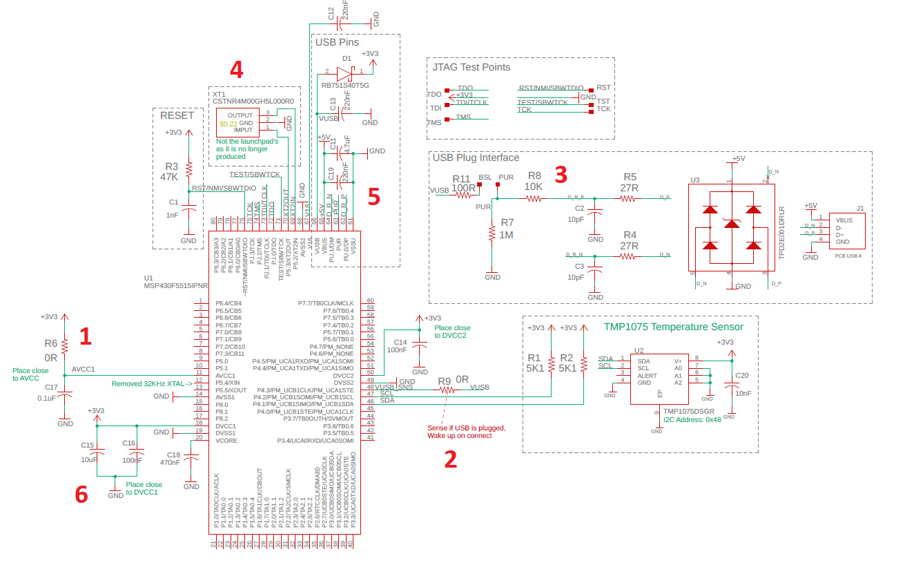
I'm building a basic USB board of MSP430F5515 and I need to verify a few component values before manufacturing as they have different values in different application notes:

1- Do I need the AVCC components if I'm not using the ADC at all?

2- If the application is battery powered (unless plugged to host), is there a software method to detect USB plug so that the MCU wakes up from LPM3 or should I do it using HW as shown in (2), (i.e. detect a rising edge of VUSB at a MCU pin)?

3- The PUR and USB resistor values have different values on the launchpad of 5529 and this document (SNOU157A - TMP1075EVM), Are both ok?

4- The Launchpad crystal is discontinued, is the following used part ok? Also the 33KHz Crystal is optional, correct?

5/6-  The decoupling Capacitor values are also different between the launchpad and the aforementioned application note, both fine?

Finally, with the below circuit, can I flash the Firmware using the USB port? Is there anything missing on this schematic for the sake of programming? I noticed the launchpad doesn't connect the JTAG pins of the Target MCU unlike simplelink family.

thanks,

  • Hi Ahmed,

    Ahmed Ibrahim31 said:
    1- Do I need the AVCC components if I'm not using the ADC at all?

    If not using the analog features you can tie AVCC to DVCC.

    Ahmed Ibrahim31 said:
    2- If the application is battery powered (unless plugged to host), is there a software method to detect USB plug so that the MCU wakes up from LPM3 or should I do it using HW as shown in (2), (i.e. detect a rising edge of VUSB at a MCU pin)?

    The USB stack does provide a method to do this, however, there is an errata, USB9, that can affect the device's ability to properly monitor the VBUS (+5V), you can use a GPIO pin and interrupt to notify you when there is a change in VBUS.  NOTE: You must provide a voltage divider to reduce the +5v to your +DVCC voltage.

    Ahmed Ibrahim31 said:
    3- The PUR and USB resistor values have different values on the launchpad of 5529 and this document (SNOU157A - TMP1075EVM), Are both ok?

    The recommended resistor value is 1.4k.  I would follow the MSP430F2259 Launchpad design.

    Ahmed Ibrahim31 said:
    4- The Launchpad crystal is discontinued, is the following used part ok? Also the 33KHz Crystal is optional, correct?

    You don't need the external 32KHz crystal.  An internal REFO 32KHz clock can be used for the ACLK and reference for the DCO.  I believe that is the default in the USB stack.

    Ahmed Ibrahim31 said:
    5/6-  The decoupling Capacitor values are also different between the launchpad and the aforementioned application note, both fine?

    Follow the MSP430F5529 Launchpad design.

    Ahmed Ibrahim31 said:
    Finally, with the below circuit, can I flash the Firmware using the USB port? Is there anything missing on this schematic for the sake of programming? I noticed the launchpad doesn't connect the JTAG pins of the Target MCU unlike simplelink family.

    For development you will need to be able to program and debug, so most definitely you need to have access to the RST and TST pins as you show in your schematic.  You don't need all the other JTAG related pins, unless you are planning on blowing the JTAG fuse for code protection.  Once your code is developed you can reflash the code over USB.  There is a python GUI in the MSP430Ware, USBLib directory that can do that.

  • Thanks for the detailed Answer!

    for 2, I'm using VUSB (The LDO Output), should it be fine?

    I assume it outputs zero Volts if the USB is not plugged in

**Attention** This is a public forum