


Other Parts Discussed in Thread: MSP430G2553
Tool/software: Code Composer Studio
Hello,
The i2c master is getting stuck on the bus busy between the MSP430F5505 i2c master connected to an MSP430G2553 i2c slave.
How to replicate the issue:
- Power down both boards.
- Power up the MSP430G2553 i2c slave device.
- Power up the MSP430F5505 i2c master device.
- Reset the MSP430G2553 or sometimes leave it running and after a while, it will fail.
The MSP430F5505 is only transmitting a single byte, it is using msp430_driverlib_2_91_13_01.
See below a good packet:
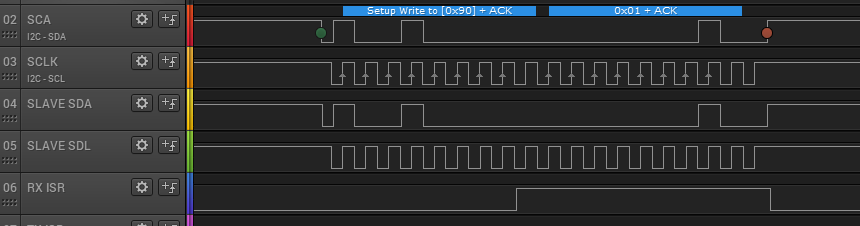
When a fault occurs the following happens:

The last packet:

At this point, the clock remains low and the device gets stuck on bus busy.

In the documentation, it specifies that the bus busy bit is set on the start condition on the START condition and removed on the END condition it is removed. I have tried timeouts and sending again but the clock stays low and again it will fail.
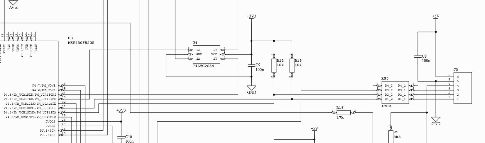
See below the hardware design of the MSP430F5505:
The slave is using the MSP-EXP43-G2 with the debugger patch pins disconnected and LED2 patch pin removed. I have tested the voltages both ends at 3.3v and 0v.
Another concern I have is the clock sometimes does the following:

Master i2c code:
uint8_t transmitData = 0x01;
void hw_i2c_master_init(void)
{
// Configure Pins for I2C
//Set P4.1 and P4.2 as Secondary Module Function Input.
receiveBufferPointer = &receiveBuffer;
/*
* Select Port 4
* Set Pin 1, 2 to input Secondary Module Function
*/
GPIO_setAsPeripheralModuleFunctionInputPin(
GPIO_PORT_P4,
GPIO_PIN1 + GPIO_PIN2
);
//Initialize Master
USCI_B_I2C_initMasterParam param = {0};
param.selectClockSource = USCI_B_I2C_CLOCKSOURCE_SMCLK;
param.i2cClk = UCS_getSMCLK();
param.dataRate = USCI_B_I2C_SET_DATA_RATE_100KBPS;
USCI_B_I2C_initMaster(USCI_B1_BASE, ¶m);
//Specify slave address
USCI_B_I2C_setSlaveAddress(USCI_B1_BASE,
SLAVE_ADDRESS
);
//Set receive mode
USCI_B_I2C_setMode(USCI_B1_BASE, USCI_B_I2C_TRANSMIT_MODE);
//Enable I2C Module to start operations
USCI_B_I2C_enable(USCI_B1_BASE);
//Enable master Receive interrupt
USCI_B_I2C_clearInterrupt(USCI_B1_BASE, USCI_B_I2C_TRANSMIT_INTERRUPT);
USCI_B_I2C_enableInterrupt(USCI_B1_BASE, USCI_B_I2C_TRANSMIT_INTERRUPT);
}
Then every 100ms the following is called:
void i2c_send_byte(uint8_t txData)
{
unsigned timeout = 10;
if(!USCI_B_I2C_isBusBusy(USCI_B1_BASE)) {
//Send single byte data.
USCI_B_I2C_masterSendSingleByteWithTimeout(USCI_B1_BASE,
transmitData, timeout
);
}
//Delay until transmission completes
while (timeout--) {
if(!USCI_B_I2C_isBusBusy(USCI_B1_BASE)) {
break;
}
}
}
The i2c slave code:
#include <msp430.h>
#include <stdint.h>

#define SLAVE_ADDR  0x48

#define MAX_BUFFER_SIZE     20

void initClockTo16MHz()
{
    if (CALBC1_16MHZ==0xFF)                  // If calibration constant erased
    {
        while(1);                               // do not load, trap CPU!!
    }
    DCOCTL = 0;                               // Select lowest DCOx and MODx settings
    BCSCTL1 = CALBC1_16MHZ;                    // Set DCO
    DCOCTL = CALDCO_16MHZ;
}

#define TIMERA_CCR0_BASE 2000

void timerA_init(void)
{
    //Set up Timer A register TACTL
    TACTL = 0x0000;     //start from all all clear
    TACTL |= BIT9;      //use SMCLK as the source
    TACTL |= BIT7;      //use prescaler 8
    TACTL |= BIT6;
    TACTL |= BIT4;      //count up to TACCR0(set below)
    TACTL |= BIT1;      //enable the interrupt
    TACTL &=~ BIT0;     //clear all pending interrupts
    TACCR0 = TIMERA_CCR0_BASE;      //use 2000 for 16 mhz
    TACCTL0 = CCIE;     //compare, capture interrupt enable
}

void initGPIO()
{
    P1DIR |= BIT4; // Set pin -> Output
    P1IE &= ~BIT4;   // Disable interrupts for pin

    P1DIR |= BIT5; // Set pin -> Output
    P1IE &= ~BIT5;   // Disable interrupts for pin

    P1SEL |= BIT6 + BIT7;                     // Assign I2C pins to USCI_B0
    P1SEL2|= BIT6 + BIT7;                     // Assign I2C pins to USCI_B0
}

void i2c_init()
{
    UCB0CTL1 |= UCSWRST;                      // Enable SW reset
    UCB0CTL0 = UCMODE_3 + UCSYNC;             // I2C Slave, synchronous mode
    UCB0I2COA = 0x48;                         // Own Address is 048h
    UCB0CTL1 &= ~UCSWRST;                     // Clear SW reset, resume operation
    UCB0I2CIE |= UCSTPIE + UCSTTIE;           // Enable STT and STP interrupt
    IE2 |= UCB0RXIE;                          // Enable RX interrupt
}


int main(void)
{
    WDTCTL = WDTPW | WDTHOLD;   // Stop watchdog timer

    initClockTo16MHz();

    initGPIO();

    timerA_init();

    i2c_init();

    __bis_SR_register(LPM0_bits + GIE);
    return 0;
}

typedef enum I2C_ModeEnum{
    IDLE_MODE,
    NACK_MODE,
    TX_REG_ADDRESS_MODE,
    RX_REG_ADDRESS_MODE,
    TX_DATA_MODE,
    RX_DATA_MODE,
    SWITCH_TO_RX_MODE,
    SWITHC_TO_TX_MODE,
    TIMEOUT_MODE
} I2C_Mode;

I2C_Mode SlaveMode = RX_REG_ADDRESS_MODE;

#pragma vector = USCIAB0TX_VECTOR
__interrupt void USCIAB0TX_ISR(void)
{
  P1OUT ^= BIT5;

  if (IFG2 & UCB0RXIFG)                 // Receive Data Interrupt
  {
      uint8_t rx_val = UCB0RXBUF;

      switch (SlaveMode)
      {
          case (RX_REG_ADDRESS_MODE):
              SlaveMode = RX_DATA_MODE;
              break;
          case (RX_DATA_MODE):
              SlaveMode = RX_REG_ADDRESS_MODE;
              //IE2 &= ~UCB0RXIE;                       // Disable RX interrupt
              //IE2 |= UCB0TXIE;                        // Enable TX interrupt
              break;
          default:
              _no_operation();
              break;
      }
  }
  else if (IFG2 & UCB0TXIFG)            // Transmit Data Interrupt
  {
      UCB0TXBUF = 0x02;

      SlaveMode = RX_REG_ADDRESS_MODE;

      //IE2 &= ~(UCB0TXIE);
      //IE2 |= UCB0RXIE;                          // Enable RX interrupt
  }
}

//------------------------------------------------------------------------------
// The USCI_B0 state ISR is used to wake up the CPU from LPM0 in order to do
// processing in the main program after data has been transmitted. LPM0 is
// only exit in case of a (re-)start or stop condition when actual data
// was transmitted.
//------------------------------------------------------------------------------
#pragma vector = USCIAB0RX_VECTOR
__interrupt void USCIAB0RX_ISR(void)
{
    P1OUT ^= BIT4;

    if (UCB0STAT & UCSTPIFG)                        //Stop or NACK Interrupt
    {
        UCB0STAT &=
            ~(UCSTTIFG + UCSTPIFG + UCNACKIFG);     //Clear START/STOP/NACK Flags
    }
    if (UCB0STAT & UCSTTIFG)
    {
        UCB0STAT &= ~(UCSTTIFG);                    //Clear START Flags
    }
}

#pragma vector = TIMER0_A0_VECTOR
__interrupt void Timer_A(void)
{
    //clear the timer interrupt
    TACTL &=~ BIT0;
}
1) How should the recovery work?
2) What can cause this fault and how can It be avoided?
Many thanks,
Jon


