This thread has been locked.

If you have a related question, please click the "Ask a related question" button in the top right corner. The newly created question will be automatically linked to this question.

MSP430FR6047: DAC7750 doesn't seem to work

Part Number: MSP430FR6047
Other Parts Discussed in Thread: DAC7750, , DAC8760

Hello;

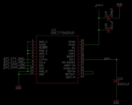
I connected DAC7750 as below;

Please see if there's anything wrong. 

The program I'm running is DAC8760_Interface I downloaded and modified to my MSP430FR6047 and DAC7750. It's a 4-20mA output type and I tried to set the output to 4 to 10mA but nothing changes on the output pin. It stays at 0.

I verified using the scope that STE, SCLK and SIMO signals are going out to DAC7750 correctly.

Please help.

Best regards,

Suh, Sukho

  • Where does one find the "DAC8760_Interface" code? I found the DACX760EVM-SW, but all I see there is what looks like LabView code.

    Alternatively, the people over at the Data Converters forum might be able to give you a quicker answer. I've found them to be very responsive.

    https://e2e.ti.com/support/data-converters/f/73

  • HI, Sukho, 

    Do you need me to forward this post to Data Converters forum or you close this and create a new post in Data Converters forum? 

    Thanks, 

    Lixin

  • Suhko,


    Looking at the schematic, do you have a precision 15kΩ resistor connected to ISET-R or are you using the internal RSET? Also is EPAD the thermal pad underneath the device? This should be connected to GND. Do you have a connection for the CLR pin? If you're not using this pin, you should tie this to GND also, just so you don't accidentally set the device to the CLEAR state. I didn't see any other connection issues, but you can also compare this with the connections in Figure 62. They won't be exactly the same, but you can compare your schematic and note differences.

    Other than that are you able to read back registers? I would try to make a change to the control register and verify that the write occurred by reading back the new setting. Note that may default values are 0x0000, so you want to change anything to verify that the register has been correctly written.

    After that, can you describe your setup configuration? I would list the values you send to the registers along with the order you're sending them. You mentioned in a previous post that you used an oscilloscope to verify your signals. Can you check that again and post your oscilloscope shots for communication? I'd want to verify writes to and reads from the device.


    Joseph Wu

**Attention** This is a public forum