Other Parts Discussed in Thread: MSP430FR2512, , CAPTIVATE-FR2633
I have been prototyping using the CAPTIVATE-PGMR and the CAPTIVATE-FR2633 board. In my final design I would like to embed the smaller MSP430FR2512 (I don't need the extra sensor ports).
I plan to program the board using the CAPTIVATE-PGMR, since it has ezFET built in. That said, I was looking at the schematic for the CAPTIVATE-FR2633, and it looks like all I really have to do to achieve that is maintain the connectivity from that development header. My plan was to essentially reproduce this pinout:
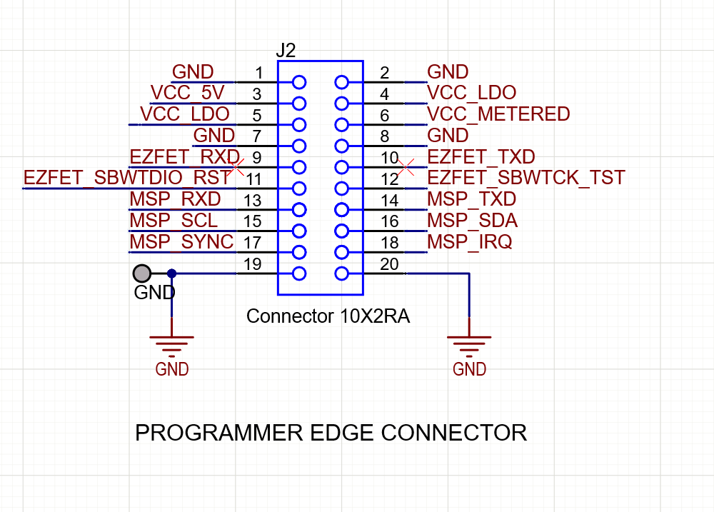
In doing so, if my board has its own power, I assume I can drop pins 3,4,5,6. As for the grounds, do I need to keep both of them? Are there any other pins I can remove? I know, for example, the IRQ pin (17/18) is needed for interactivity with the design studio.
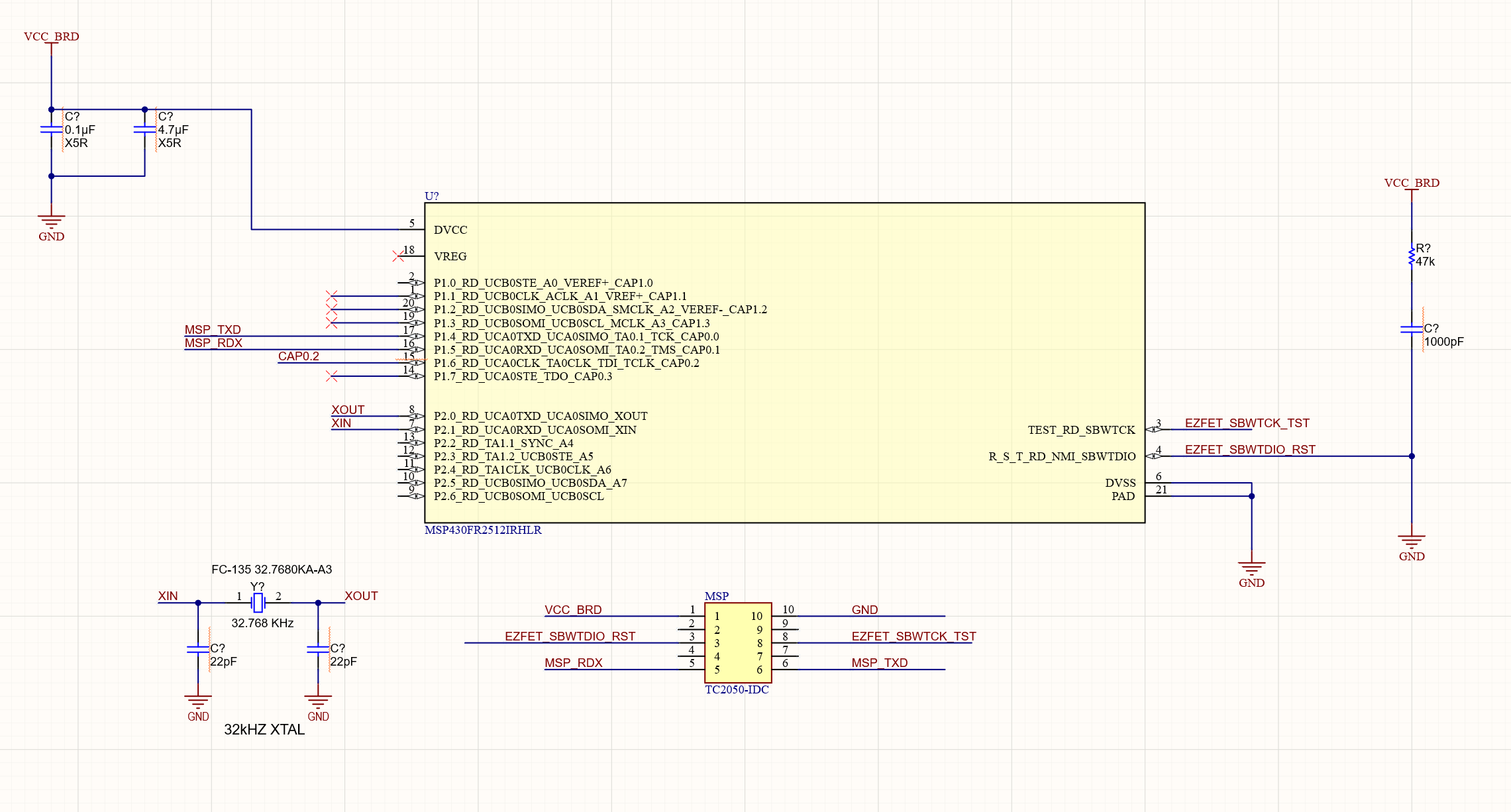
Are there other things I should be considering? It looks like the only other thing the board needs is the crystal, for which I will using the following design:

Thanks!