Other Parts Discussed in Thread: EV2400, TXS0108E
Folks:
The MSP430F5359 has three USCI peripherals (USCI_B0, USCI_B1, and USCI_B2) that can
operate in I²C Bus mode. USCI_B0 appears on the P2 "Portmap" pins; USCI_B1 appears on
P8.5 and P8.6, and USCI_B2 appears on P9.5 and P9.6.
For USCI_B0, the Data Sheet makes it explicit that I2C Clock and I2C Data are "open drain"
signals. (They could be real open-drain drivers or just a clever simulation that only switches "on"
the totem pole when "driving low"; it makes no difference.)
But for USCI_B1 and _B2, both the Data Sheet and the Family User's Guide are relatively
silent on whether or not P8.5 and P8.6 or P9.5 and P9.6 become "open drain" drivers when
the USCI peripheral is selected and placed into I²C Bus mode. We have this diagram in the
Family User's Guide that illustrates "open drain" drivers:

But no other mention of "open drain" except in the context of the "Port Mapping" functionality.
And the Data Sheet offers up this diagram for the P9.x pin circuitry (and an equivalent
diagram for the P8.x pin circuitry):

Again, no obvious clue that the P9.5 and P.6 pins (or P8.5 and P8.6 pins) can be
"open drain" when the pins are operating in I²C Bus mode.
I'm confident that they must be "open drain" (else the I²C Bus wouldn't operate
properly, especially for "clock stretching"), but I'd like you (TI) to confirm this
(and probably, to update the various documentation to reflect this).
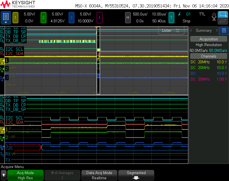
I ask for this because we're having some trouble using an ST2378E magic
bidirectional level converter on the MSP430's I²C Bus. We operate our MSP430
at 2.5V and use this chip to accommodate the 3.3V connection to TI's EV2400
Battery Gauge programming pod. With the pod disconnected (i.e., open circuits
on the 3.3V side of the level translator, pulled-up by the chip's internal 9KΩ
pull-up resistors), we're getting intermittent cross-conduction, at least while the
MSP430 is trying to drive I2C SDA low. Because of this, I want to be absolutely
sure I understand the MSP430's pin architecture vis-a-vis driving the I²C Bus.
(As an aside, I also wonder if TI's TXS0108E version of the magic bidirectional
level converter works better than ST's version. If you've got any advice in that
regard, please feel free to offer it!)
Atlant