This thread has been locked.

If you have a related question, please click the "Ask a related question" button in the top right corner. The newly created question will be automatically linked to this question.

MSP-FET: MSP-GANG works, MSP-FET does not

Part Number: MSP-FET
Other Parts Discussed in Thread: MSP-GANG, UNIFLASH, MSP430F2013,

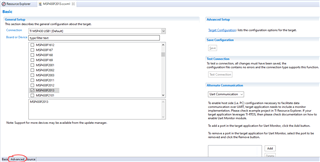
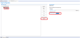
I'm working on a design with a MSP430F2013, and am trying to program/debug it with an MSP-FET, but receive an error saying "Error connecting to the target: Unknown device." Behavior is the same using UniFlash and Code Composer Studio. However, the MSP-GANG works using the MSP-GANG utility. I've attached the relevant parts of the schematic. In both cases, I've set the programmer to supply 3.0V and am using the same cable/interface and firmware file.

Can you help me figure out what I might try to get the MSP-FET to recognize my device?

MSP-Gang Hookup.pdf

  • Hi Adam,

    Thanks for your detailed post. I compared your schematic with the recommended circuit in Figure 2-1. Signal Connections for 4-Wire JTAG Communication in the MSP430 Hardware Tools User's Guide. In your design, you've connected the pull-up resistor and pull-down capacitor to the !RST pin of the MSP430F2013, but you've connected that pin to the TDO/TDI pin (1) of the MSP-FET connector instead of the !RST pin (11). I assume this is causing the issue.

    Regards,

    James

  • It looks like you've mixed SBW and 4-wire JTAG connections. If you're trying to use SBW, please refer to Figure 2-2. Signal Connections for 2-Wire JTAG Communication (Spy-Bi-Wire) Used by MSP430F2xx, MSP430G2xx, and MSP430F4xx Devices in the MSP430 Hardware Tools User's Guide.

    Regards,

    James

  • Yes, the design is set up to use 2-wire JTAG (SBW).

    I'm having trouble finding a wiring problem.  According to Figure 2-2, the microcontroller's !RST/NMI/SBWTDIO pin should connect to the MSP-FET's TDO/TDI pin, with a resistor and capacitor, while the MSP-FET's RST pin remains unconnected.  I think that's how my circuit is set up.

    What am I missing?

  • Oh, ok!  But there's this confusing footnote C on Figure 2-2:

    "R2 protects the JTAG debug interface TCK signal from the JTAG security fuse blow voltage that is supplied by the TEST/VPP pin during the fuse blow process. If fuse blow functionality is not needed, R2 is not required (populate 0 Ω) and do not connect TEST/VPP to TEST/ SBWTCK."

    I'm not supporting fuse blow functionality.  Is the TEST/VPP pin used for something other than blowing the fuse?  In light of footnote C, what should I connect the MSP-FET's TCK pin to?  Isn't it required for SBW?

    Thanks for your patience!

  • Hi Adam,

    Thanks for YOUR patience. I was moving too quickly today! I think the 4-wire JTAG net names in SBW configuration confused me. For SBW, your connections are correct. The TEST/SBWTCK pin should be connected to Pin 7 on CN1 like you have it. I'll update my earlier post to reflect that. If you're not planning to blow the JTAG fuse, you can make a direct connection between TEST/SBWTCK and Pin 7 on CN1. No need for the TEST/VPP connection. If you think you may need to blow the JTAG fuse later in your design, you may want to consider adding a 0 Ohm placeholder for R2 as the footnote mentions. You would also need another resistor placeholder (that's not populated) to connect TEST/VPP to TEST/SBWTCK.

    Since your connections are correct, let's try to resolve your issue. Here are some things to check/change:

    • Make sure your 14-pin ribbon cable or jumper wires that connects the MSP-FET and the target socket module do not exceed 8 inches (20 centimeters) in length.
    • Change R1 to 47 kOhm.
    • Try slowing down the SBW clock speed.
    • Try changing C2 to 0.1 nF. The SBW interface is much more sensitive to parasitic capacitance than 4-wire JTAG.

    I hope these recommendations help you resolve the issue quickly. 

    Regards,

    James

  • I received some good advice here, but have not tried it yet.  I'll post again when I do!

  • Thanks Adam. Let us know what you find!

  • I was able to try the following:

    • Changed R1 to 47kOhm.
    • Changed C2 to 0.1nF.
    • Programming cable is less than 8 inches.

    There was no change.  I can program using the MSP-GANG in our factory (even at the highest SBW speed setting), but not with the MSP-FET on my desk using Uniflash or Code Composer Studio.

    Is there a way to set the SBW speed setting in Uniflash or Code Composer Studio?  Do you have to select SBW or JTAG somewhere?  Could my antivirus software be interfering somehow?

    Thanks,

    Adam J.

  • Hi Adam,

    Thanks for the update. I'm sorry those suggestions didn't work. Here are some more to help narrow down the root cause:

    • Is the orientation of the MSP-FET's 14-pin connector the same as the MSP-GANG? I think this error would happen if it was rotated 180 degrees.
    • Do you have any other TI boards or EVMs that you could try programming with your PC and the MSP-FET to validate that portion works correctly?
    • Can you try a different PC to rule out anti-virus interference? Don't use a USB hub either.
    • Can you try powering your board with an external bench supply or battery? Perhaps the board is exceeding the MSP-FET's maximum current supply. You'll want to connect Pin 4 (VCC_TARGET) of the MSP-FET to VCC rather than Pin 2 (VCC_TOOL).

    To slow down the SBW clock in CCS, double-click the .ccxml file under your CCS project folder > targetConfigs folder. Beside the Basic tab at the bottom of that window, click the Advanced tab.

    Click MSP430 at the bottom of the tree. On the right under CPU Properties, you'll see JTAG/SBW Speed. Change it to Slow. Then, click Save and try to program the device.

    Regards,

    James

**Attention** This is a public forum