This thread has been locked.

If you have a related question, please click the "Ask a related question" button in the top right corner. The newly created question will be automatically linked to this question.

MSP-EXP430FR2355: Issue with Clock setting 24Mhz from external crystal 12Mhz

Part Number: MSP-EXP430FR2355

Hello Team,

We are working on our custom board to generate 24Mhz from external 12Mhz crystal we observing strange behavior of clock source. When we toggle LED in while loop we are getting period 806 nano seconds(this is calculated based on toggle cycles(16 * 1/assuming 20Mhz clk)). may be we get strucked in configuration. Can anyone please look into configuration we have done and may be we mistaken in configuration. Please any help would be very thankful.

int main(void)
{
    WDTCTL = WDTPW | WDTHOLD;   // stop 'Watch-dog' timer
    // Watch-dog will be configured for >10ms and enabled!

    Init_Sys_Clock();   // initialize System Clocks
    Init_GPIOs();       // initialize GPIOs

     while (1)
    {
         P6OUT ^= BIT6;
    }
}

void Init_Sys_Clock(void)
{
    // Setting clock to 24Mhz
    P2SEL1 |= BIT7;          // P2.7: crystal pins

    __bis_SR_register(SCG0);        // disable FLL
    CSCTL1 = DCORSEL_7;             // Set DCO = 24MHz
    CSCTL2 = FLLD_0 + 1;          // DCOCLKDIV = 24MHz

    __delay_cycles(3);
    __bic_SR_register(SCG0);        // enable FLL

     CSCTL4 = SELMS__XT1CLK | SELA__XT1CLK; // set XT1 (12Mhz) as ACLK source
                                            // default DCOCLKDIV as MCLK and SMCLK source
     CSCTL6 = XT1BYPASS_1 | XTS_1 | DIVA_8 | XT1HFFREQ_2 | XT1AGCOFF_1 | XT1DRIVE_3;
     
}

  • As I read data sheet (SLASEC4D) Sec 6.10.2, the FLL really expects a low-frequency reference (yeah, you'd think Table 5-5 would say this more explicitly). I suppose you could use FLLREFDIV=512 and work with 12MHz/512=23437.5Hz.

  • Thank you for the reply Bruce,

    But still i'm facing some issues,

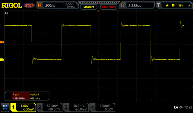
    1. Toggling LED in while(1) giving 628nsec which means while running at 25.3Mhz is it true? When i done this in launchpad its getting 666nsec so, 666nsec / 16 = 41.6nsec which is 24Mhz. I'm totally confused here how can i get 25Mhz ?

    void Init_Sys_Clock(void)
    {
        // Setting clock to 24Mhz
        P2SEL1 |= BIT7;          //P2.7: crystal pin
    
        FRCTL0 = FRCTLPW | NWAITS_2;    // FRAM: 2 wait states
    
        __bis_SR_register(SCG0);        // disable FLL
        CSCTL3 = SELREF__XT1CLK | FLLREFDIV_5; // Set XT1 as FLL reference source
        //CSCTL0 = 0;                     // clear DCO and MOD registers
        CSCTL1 = DCORSEL_7;             // Set DCO = 24MHz
        CSCTL2 = FLLD_0 + 1024;          // DCOCLKDIV = 24MHz
    
        __delay_cycles(3);
        __bic_SR_register(SCG0);        // enable FLL
    
         CSCTL4 = SELMS__XT1CLK | SELA__XT1CLK; // set XT1 (12Mhz) as ACLK source
                                                 // default DCOCLKDIV as MCLK and SMCLK source
         CSCTL6 = XT1AGCOFF_1 | XT1HFFREQ_2 | XT1BYPASS_1 | XTS_1 | XT1DRIVE_3 | DIVA_8;
    }


    Above is toggle LED signal in while(1).

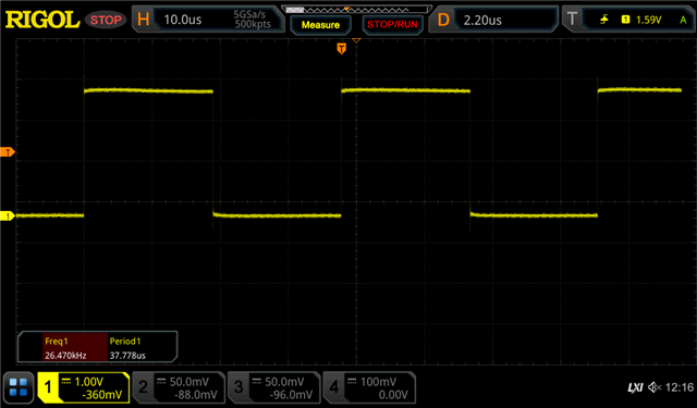
    2. Timer configured at CCR0 = 480 should give 20usec interrupt but giving 19usec. Is this because of 25Mhz?

    void Init_Timer0 (void)
    {
        TB0CCR0 = 480;                     // 20usec(10-on,10-off) for 24Mhz
        TB0CTL = TBSSEL__SMCLK | MC_1;          // SMCLK, Up mode
        TB0CCTL0 |= CCIE;                       // TBCCR0 interrupt enabled
    
        __bis_SR_register(GIE);                 // Enter LPM0 w/ interrupt
    }
    

    Below signal is the timer interrupt

    3. With this configuration i'm facing verification failed error very frequently like 3/5 debug times its too annoying but when i run with low clock configuration there is no failed error like previous. What is the reason to cause like this? Did i select wrong crystal like 12Mhz? can msp430 really configurable by 12Mhz to 24Mhz?

    Please check the configurations attached. Any help would be very thankful.

  • > CSCTL2 = FLLD_0 + 1024;          // DCOCLKDIV = 24MHz

    The FLLN field is only 10 bits, so 1024 won't fit, and this sets FLLN=0. As it happens, the operating value is actually (FLLN+1), so try:

    > CSCTL2 = FLLD_0 + (1024-1);      // DCOCLKDIV = 24MHz

    If you can reach pin P3.4 or P1.0, you can configure it to put out SMCLK, which might make testing a little simpler. [Ref data sheet Tables 6-65 and 6-63]. I don't have the equipment to try this myself.

  • Thank you for the reply Bruce,

    We have done the configuration as you suggested but we observed the same thing we mentioned as previous.

    One more thing we observed as SMCLK is 25.5Mhz at PIN how is that possible? So, we suspected something is going wrong with modulation. so we set MOD = 1 and DCO tap = 238 and found SMCLK is 24Mhz we acheived it but can't understand what is DCO tap and MOD also how it is creating 24Mhz without them (CSCTL = 0) we are observing 19.8Mhz even though configured for 24Mhz.

    We even divided XT1 further to 256 and kept FLLN as 511 still we observed 19.8Mhz. So, can't we acheive 24Mhz without modulation ?

    {
        P2SEL1 |= BIT7;          // P2.7: oscillator pins
    
        __bis_SR_register(SCG0);        // disable FLL
        CSCTL3 = SELREF__XT1CLK | FLLREFDIV_4;       // Set XT1 as FLL reference source
        CSCTL0 = 0;                     // clear DCO and MOD registers
        CSCTL1 = DCORSEL_7;             // Set DCO = 24MHz
        CSCTL2 = FLLD_0 + (511);          // DCOCLKDIV = 24MHz
    
        __delay_cycles(3);
        __bic_SR_register(SCG0);        // enable FLL
    
         CSCTL4 = SELMS__XT1CLK | SELA__XT1CLK; // set XT1 (12Mhz) as ACLK source
                                                 // default DCOCLKDIV as MCLK and SMCLK source
         CSCTL6 = XT1HFFREQ_2 | XT1BYPASS_1 | XTS_1;
    }

    Please re-check the configuration, Please note we are using oscillator of 12Mhz.

  • >     CSCTL4 = SELMS__XT1CLK | SELA__XT1CLK;

    This sets MCLK, SMCLK, and ACLK to be the crystal, so it seems like it doesn't matter what the DCO is doing. I suppose the FLL keeps running, so you can watch the DCO settings in CSCTL0.

    The fact that (based on the SMCLK pin output) SMCLK is in fact being affected by the DCO setting suggests that the clock input on P2.6 is faulting, and SMCLK is failing (back) over to the DCO. Is XT1OFFG set?

  • Yes Bruce we observed that XT1OFFG is in set and remains. What is the exact reason to happen like this ? 
    On what cases XT1 oscillator fault occurs?

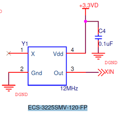
    We are using ECS-3225SMV-120-FP (12Mhz oscillator). you can see the below schematic of oscillator.

    Please give me a checklist what i can check where and why fault is occurring? 

  • 1) If you can reach it, probe the XIN pin to make sure the clock waveform looks the way you expect.

    2) It appears the XT1 assignment doesn't automatically switch back after a fault -- you have to explicitly clear the XT1OFFG. [Ref UG (SLAU445I) Sec 3.2.13 and 3.2]. This is different from e.g. the F2 series. You should clear XT1OFFG in a loop, as seen in Example msp430fr235x_CS_10.c:

    https://dev.ti.com/tirex/explore/node?node=AA-Phlkv5QEyfbuoKLRxIA__IOGqZri__LATEST

    While you're in there, make sure you're doing things in the same order as the Example. I suspect that in at least some cases the ordering matters.

  • Thank you for the reply Bruce,

    We found that below configuration is working fine.

    void Init_Sys_Clock(void)
    {
        // Setting clock to 24Mhz
        P2SEL1 |= BIT7;          // P2.7: crystal pins
    
        __bis_SR_register(SCG0);        // disable FLL
        CSCTL3 = SELREF__XT1CLK | FLLREFDIV_4;  // Set XT1 as FLL reference source
        CSCTL0 = 0;                     // clear DCO and MOD registers
        CSCTL1 = DCORSEL_7;             // Set DCO = 24MHz
        CSCTL2 = FLLD_0 + 511;          // DCOCLKDIV = 24MHz
        CSCTL6 = XT1BYPASS_1 | XTS_1;
        __delay_cycles(3);
        __bic_SR_register(SCG0);        // enable FLL
    
        do
        {
            CSCTL7 &= ~(XT1OFFG | DCOFFG);  // Clear XT1 and DCO fault flag
            SFRIFG1 &= ~OFIFG;
        }
        while (SFRIFG1 & OFIFG);        // Test oscillator fault flag
         while (CSCTL7 & (FLLUNLOCK0 | FLLUNLOCK1)); // wait till FLL locked
         CSCTL4 = SELMS__DCOCLKDIV | SELA__XT1CLK; // set XT1 (12Mhz) as ACLK source
                                                 // default DCOCLKDIV as MCLK and SMCLK source
    }

    Just by interchanging flag check after configuration resolved issue. why?

    In the datasheet it is mentioned for XT1 start up time is 1.1ms in HF mode can that some how related to the issue?

    Do we need to wait sometime after XT1 configured oscillator as reference ?

  • Hello Bruce,

    Please confirm on this we are waiting for your reply.

  • I didn't realize you were waiting for me.

    UG Sections 3.2.13 and 3.2, taken together, say that (a) Once XT1OFFG is set, it doesn't clear automatically and (b) You can't assign XT1 to a clock (e.g. FLLREF) until XT1OFFG (and OFIFG) are cleared. In the User Guides for some other series, there's an explicit statement something like (paraphrasing) "XT1OFFG [or equivalent] will always be set at startup, since the startup PSEL settings disable the oscillator". I don't see that sentence here, but I suspect it still applies.

    It looks like [Ref Fig 3-2 and Sec 3.2.13, second NOTE:] the same fault-checking is done on an external oscillator (XT1BYPASS=1) as for a crystal, so one supposes the 1.1ms (typical) would apply. This is done via an oscillation count, so a faster oscillator would be expected to start up quicker.

    Once XT1OFFG (and OFIFG) are switched off and stay off, the oscillator is ready and there's no reason to wait any longer. If the oscillator faults later, that's a separate incident.

    There's no explicit indicator (IFG) for the event where the fault condition clears (I'm not sure it's even an event, rather the absence of one), so you have to poll. I do see the ENSTFCNT1 bit, which isn't really explained, but seems to (maybe) turn off the fault-checking logic. If you have total faith in your external oscillator, it may be that setting ENSTFCNT1=0 would reduce your poll time.

**Attention** This is a public forum