From Resource explorer, I import the msp430fr69xx_eusci_uart_standard_transceiver C project. I jumper P2.- and P2.1 pins to RX and TX on the launchpad and from the terminal, I can send and receive the correct character.
Then I import the eusci_a_uart_ex1_loopbackAdvanced project (driverlib) I copy the interrupt functions from the above project but I got many errors on the serial port.
I have some questions.
a) the code below from the working project
// Configure UART
P2SEL0 |= BIT0 | BIT1; // USCI_A0 UART operation
P2SEL1 &= ~(BIT0 | BIT1);
UCA0CTLW0 |= UCSSEL__ACLK; // CLK = ACLK
// Baud Rate calculation
// 32768/(9600) = 3.4133
// Fractional portion = 0.4133
// Use Table 24-5 in Family User Guide
UCA0BR0 = 3; // 32768/9600
UCA0BR1 = 0;
UCA0MCTLW |= 0x9200; //0x9200 is UCBRSx = 0x92
UCA0CTLW0 &= ~UCSWRST; // Initialize eUSCI
UCA0IE |= UCRXIE; // Enable USCI_A0 RX interrupt
As I can see the code below -using the driverlib- do the same but it has too many errors on the serial port
GPIO_setAsPeripheralModuleFunctionInputPin(
GPIO_PORT_P2,
GPIO_PIN0 + GPIO_PIN1,
GPIO_SECONDARY_MODULE_FUNCTION
);
// Configure UART
EUSCI_A_UART_initParam param = {0};
param.selectClockSource = EUSCI_A_UART_CLOCKSOURCE_ACLK;
param.clockPrescalar = 3;
param.firstModReg = 0;
param.secondModReg = 0x92; // the source code has the value 92 not 0x92 is it a typograhic error?
param.parity = EUSCI_A_UART_NO_PARITY;
param.msborLsbFirst = EUSCI_A_UART_LSB_FIRST;
param.numberofStopBits = EUSCI_A_UART_ONE_STOP_BIT;
param.uartMode = EUSCI_A_UART_MODE;
param.overSampling = EUSCI_A_UART_LOW_FREQUENCY_BAUDRATE_GENERATION;
if (STATUS_FAIL == EUSCI_A_UART_init(EUSCI_A0_BASE, ¶m)) {
return;
}
EUSCI_A_UART_enable(EUSCI_A0_BASE);
EUSCI_A_UART_clearInterrupt(EUSCI_A0_BASE, EUSCI_A_UART_RECEIVE_INTERRUPT);
// Enable USCI_A0 RX interrupt
EUSCI_A_UART_enableInterrupt(EUSCI_A0_BASE,
EUSCI_A_UART_RECEIVE_INTERRUPT); // Enable interrupt
the rest of the code is the same at two projects
__enable_interrupt();
while (1)
{
__bis_SR_register(LPM3_bits + GIE); // Since ACLK is source, enter LPM3, interrupts enabled
}
}
//******************************************************************************
//
//This is the USCI_A0 interrupt vector service routine.
//
//******************************************************************************
#if defined(__TI_COMPILER_VERSION__) || defined(__IAR_SYSTEMS_ICC__)
#pragma vector=USCI_A0_VECTOR
__interrupt void USCI_A0_ISR(void)
#elif defined(__GNUC__)
void __attribute__ ((interrupt(USCI_A0_VECTOR))) USCI_A0_ISR (void)
#else
#error Compiler not supported!
#endif
{
switch(__even_in_range(UCA0IV, USCI_UART_UCTXCPTIFG))
{
case USCI_NONE: break;
case USCI_UART_UCRXIFG:
while(!(UCA0IFG&UCTXIFG));
UCA0TXBUF = UCA0RXBUF;
// P1OUT ^=BIT0;
__no_operation();
break;
case USCI_UART_UCTXIFG: break;
case USCI_UART_UCSTTIFG: break;
case USCI_UART_UCTXCPTIFG: break;
}
}
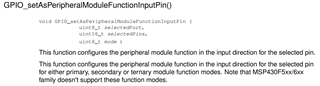
b) GPIO_setAsPeripheralModuleFunctionInputPin at
driverlib ver 2.91.13.01 the accepts 2 params
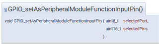
can you give me more information about that?
c) I want to use Uart_A1 ( P3.4 and P3.5 ) which is the piece of code to do the same for P3.4 and P3.5 with the drivelib?