This thread has been locked.

If you have a related question, please click the "Ask a related question" button in the top right corner. The newly created question will be automatically linked to this question.

MSP430FR6043: USS GAS prototype

Part Number: MSP430FR6043
Other Parts Discussed in Thread: TIDM-02003, EVM430-FR6043

Hi,

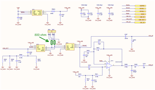
I have a custom board based on the GAS EVM.
I use MSP430FR6043 along with 200k transducers.
I have my prototype connected to the USS GUI in the same way as the TI's GAS EVM.

Based on that, I have some questions and problems to discuss.

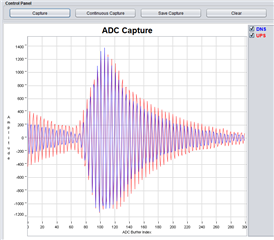
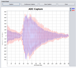
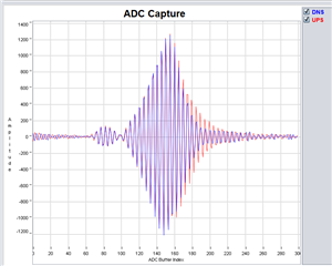
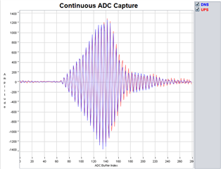
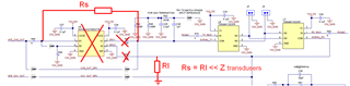
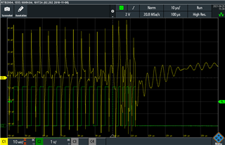
1) I experience quite big noise on the receiving channel during burst transmission. These unwanted spikes are reflected from the receiving transducer while the burst ends and creates a noise floor for receiving signal. I use Rterm=820 ohm.
Do you experience the same? What is the effective way to reduce this?


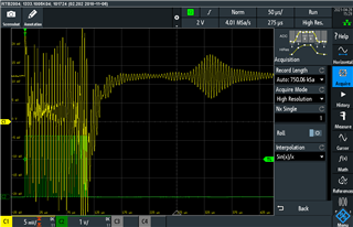
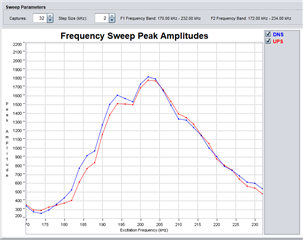
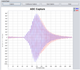
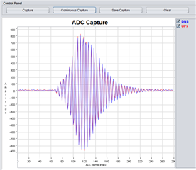
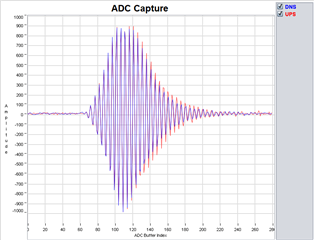
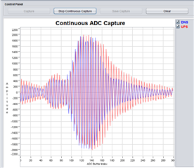
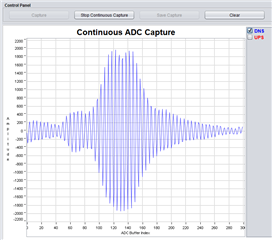
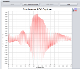
2) The received signal looks as presented below. The UPS and DNS signals are not symmetrical and are not identical.
Is this shape correct? Is there anything I can adjust in parameters to get better shape?


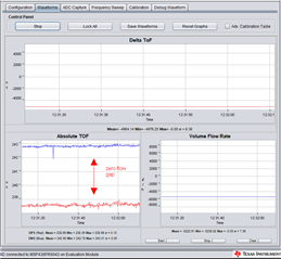
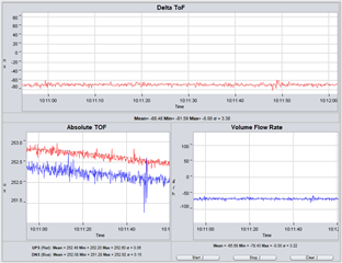
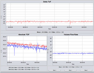
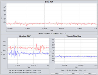
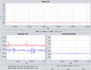
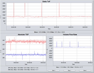
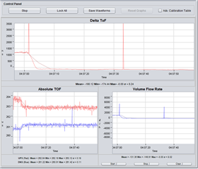
3) I observe spikes in both TOF and delta TOF, as presented below.
What is the source of these outliers? Do you experience a similar problem? How to troubleshoot this?


4) When there is no gas flow inside the pipe, I get a non-zero delta TOF.
Is this result normal and caused, e.g., by some irregularities in transducers mounting or accuracy in reflection angles?
How to overcome this? Can I adjust some parameters to eliminate this effect?


I fully understand that some of my questions are pretty open, but my goal is to discuss the results and get feedback from more experienced people on the subject.

Regards
Adam

  • Hi Adam,

    Please find some answers below:

    1. There will be noise on the receive side during transmission.  There are specific layout considerations mentioned in the TIDM-02003 user's guide which should be taken into consideration to mitigate this noise.  Can you share more information about your board design? 

    2. The excitation frequency range for your transducers needs to be adjusted based on the frequency response of the transducers you are using.  You can find more information about all of this with links to relevant documents here: https://dev.ti.com/tirex/explore/content/msp_academy_msp430_1_00_04_11/modules/msp430/msp430_USS_training/msp430_uss_training.html#-introduction

    3. There is excitation noise coming into your signal as can be seen from your captures in 1.  In order to reduce this noise, you can set the F2 transmit frequency to a higher frequency.  As discussed in the link above, you should start with an initial configuration of 8 pulses.

    4.  The issues you are seeing here are related to the excitation noise coming into your signal. Please post a frequency sweep of your transducers as described in the link above to determine the best excitation parameters for the transducers you are using.

    BR,
    Leo

  • Hi Leo,

    Thank you for your detailed answer.
    I have to think it over, and I'll come back to you in the next week.

    In the meantime, I checked TIDM-02003 for PCB layout considerations, and I found "4.3 PCB Layout Recommendations".
    Unfortunately, the given link is no longer active. I was trying to browse this on the Internet, but without success.

    Do you have this link or this application note?
    "PCB Design Guidelines for Gas Metering With MSP430FR6043"

    Regards,
    Adam

  • Can you share more information about your board design?

    Please find design files attached.

  • Hi Adam,

    I'll need to consult with some folks to see what happened with regards to this link. In the mean time, I would propose that you conduct a frequency sweep as described in the link I sent you. It might be possible to resolve the issues you are seeing by simply adjusting the F1 and F2 transmit frequencies and reducing the number of excitation pulses to 8.

    BR,

    Leo

  • Hi Leo,

    Please find the frequency sweep measurements for the burst that comprises eight pulses.

    The shape is selective and very consistent for up / down measurements. In addition, it confirms the nominal resonance frequency of 200 kHz.

    According to the link you sent,
    - I found a peak frequency = 200 kHz.
    - I found F1 = 200 - 10 - 190 kHz
    - I found F2 = 190 + 50 = 240 kHz.

    See the following ADC capture for these parameters (190-240 kHz, 8 pulses).

    Unfortunately, it doesn't change too much in the ToF measurements.

    There is still a massive gap between up and down ToF.
    I would say that remarks/problems from the original post are still valid.
    What can we do next to diagnose the source of these problems?

    Regards
    Adam

  • Hi Adam,

    Can you post your configuration tabs?

    BR,
    Leo

  • Hi Adam,

    It looks like the transducers are continuing to ring after excitation. Try increasing F2 to 290kHz in order to reduce the excitation energy.  If this doesn't reduce the "ring down", I would recommend soldering a resistor across the transducer terminals to dampen the transducer after excitation. (maybe 1k) 

    Do you see similar "ring down" in ADC captures with the MSP430FR6043 EVM?

    BR,
    Leo

  • Hi Leo,

    Extending F2 to 290k doesn't help.

    Adding Rbias reduces this ringing to the acceptable level.

    Rbias = 2.2k; Rterm = 800ohm; 160-240kHz; 8 pulses

    The resonant frequency has shifted (Rbias = 2.2k; 8 pulses).

    Rbias = 2.2k; Rterm = 800ohm; 160-240kHz; 20 pulses

    Rbias = 1k; Rterm = 800ohm; 160-240kHz; 8 pulses

    Frequency sweep (Rbias = 1k, 8 pulses)

    Rbias = 1k; Rterm = 800ohm; 160-240kHz; 20 pulses

    Once the ringing was reduced, the measurements are stable (there are no glitches), but still delta ToF >10ns (for the best parameter set I found). What can we do next to get to 0ns (mean ToF) for a zero-flow scenario?

    Do you see similar "ring down" in ADC captures with the MSP430FR6043 EVM?

    I don't have one, but our prototype is highly inspired by the original one.

    BTW. Do you have any information regarding this missing application note?

    Regards
    Adam

  • One more remark...

    It looks like the transducers are continuing to ring after excitation.

    This ringing is on the receiving side (CH_IN).

    • The outgoing square wave creates switching noise on the GND and power rails
    • This noise is transferred to the receiving transducer
    • The receiving transducer continues to ring after excitation ends
  • Hi Adam,

    I'll need to consult my colleague who is returning later this week on the PCB layout recommendations. Do you have both ends of your tube sealed and is everything shielded as described in the link provided above?

    BR,
    Leo

  • The pipe is sealed on both ends.
    I don't have a cage yet, working on it.
    I think the cage will be ready at the end of the following week.

    I think shield can affect sigma and not the mean value.
    While waiting for the cage, I'm preparing the next PCB, so I want to gather as much information as possible.

    Regards
    Adam

  • Hi Adam,

    I wouldn't expect to see that little bit of energy at the beginning of excitation.  Can you try shifting your start excitation(F1) to 180kHz to see if it's still there?

    BR,
    Leo

  • Rbias = 1k; Rterm = 800ohm; 180-240kHz; 8 pulses

    Rbias = 1k; Rterm = 800ohm; 180-240kHz; 20 pulses

  • Hi Leo,

    Let me summarize our board's main changes and known bugs compared to the TI's USS EVM. I think it would help to analyze the problem.
    1) I don't have a bus transceiver 74LVC2T45 used to increase the amplitude of the output signal.
    2) I lost Rterm on the TX path. Therefore, I have two Rterm soldered to the connector where transducers are connected (gold pin connector).
    3) I don't have the highlighted bias resistor. Instead, I have two Rbias (1k) connected to the ground where transducers are connected (gold pin connector).


    Regards
    Adam

  • Hi Adam,

    We recommend against removing the transceiver because the Tx and Rx circuits are designed to be impedance matched so that when we look back from either transducer, the impedances are the same.  This paper explains why it's important to match Tx and Rx impedances:

    https://ieeexplore.ieee.org/stamp/stamp.jsp?arnumber=4409678

    BR,

    Leo

  • Hi Leo,

    1)

    This paper explains why it's important to match Tx and Rx

    Thank you for the tip.

    2)

    We recommend against removing the transceiver

    Would you shed some light? Why do you think this transceiver is essential here?
    I made manual changes to my PCB, and I have the circuit equivalent to the following taken from EVM430-FR6043 but without this transceiver. The zero-flow delta ToF had dropped significantly to 2-3ns (without too much work and any parameter adjustments).

    3)
    Do you have any information regarding this missing application note?
    I want to make changes to my PCB and would like to see what the recommendations are.

    Regards
    Adam

  • Hi Adam,

    In the development of a gas meter, you will see significant attenuation in the ultrasonic signal when testing in methane(ie. an additional 25dB).  This will have a negative effect on your standard deviation.  A simple way to address this is to increase the excitation voltage.  This can be done without significant modification via the transceiver.

    We recommend following the EVM layout as closely as possible.  Important points for the USS part will be:

    • Keep USS signal traces as short as possible.
    • Do not cross USS signal IN/OUT traces
    • USS traces from IC to amplifier circuit should be symmetric.  If symmetric is not possible, trace length should be the same.  On the EVM, this is from the chip to J9.
    • Keep USSXT close to IC and short traces.

    There are also more general layout guidelines in the datasheet, section 10.

    https://www.ti.com/lit/ds/symlink/msp430fr6043.pdf

    Because these recommendations are straightforward, the referenced app note was never published.

    BR,
    Leo

  • Hi Leo

    I thought I had finished this topic, but I have doubts about one of your recommendations.

    USS traces from IC to amplifier circuit should be symmetric.  If symmetric is not possible, trace length should be the same.  On the EVM, this is from the chip to J9.

    I don't know if I understand this correctly.
    Which of the signal paths should be of the same length?

    USS traces from IC to amplifier circuit should be symmetric.

    There is only one amplifier and only one path. Do you mean these two paths:
    CH0_OUT to U9 (pin 7)
    U10 (pin 1) to CH0_IN

    Assuming the paths from J5/J6 to U7/U8 (pin 4,5) are symmetrical, do we have to match the length of these paths:
    U9 (pin 2) to U8 (pin 5)
    U10 (pin 3) to U7 (pin 5)

    Regards
    Adam

  • Hi Adam,

    The goal is that the impedance when looking back into the circuit from one transducer should be as close as possible to the impedance of the circuit when looking back from other transducer.

    BR,
    Leo 

**Attention** This is a public forum