This thread has been locked.

If you have a related question, please click the "Ask a related question" button in the top right corner. The newly created question will be automatically linked to this question.

BOR and VCC vs DCO Freq. Disscussion

Other Parts Discussed in Thread: MSP430G2553

Hey Everyone,

I have seen a lot of questions about the Brownout Reset (BOR) circuitry and recently ran into it again myself.  There are many applications where the BOR works great, but also many applications where the BOR might not be sufficient.  This information is all documented, but I'm just trying to bring these resources together. 

Background:

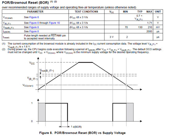
The BOR is a very simple circuit that holds the MSP430 in reset until VCC reaches a threshold voltage.  As seen below, in Figure 8, the BOR threshold is max 1.71 V + 210 mV.  It has been seen as low as 1.5V.  When VCC is rising and reaches this threshold, Reset is released after a small delay, Td(bor), which is max 2ms in this case.  There is a time delay to allow VCC to rise to a reasonable voltage before releasing reset.  This is what allows the BOR thershold to vary from chip to chip. 

When VCC is falling, the BOR puts the MSP430 in reset once VCC hits the BOR threshold without the V_hys added in, so max 1.71V. 

Risky Situations:

1.  VCC rises slowly

a.  BOR can release reset before you are at your expected voltage

2.  VCC could dip or VCC falls slowly enough that power could be re-applied before hitting VCC start (MSP430 not fully off)

a.  MSP could run an unexpected voltage, before BOR reset.  Without power cycle, there could be potential problems.

Potential Problem:

Mclk vs VCC: This violation is when running the DCO at a frequency with a minimum required VCC, while that VCC condition is not met.  When this happens, the MSP is being run in violation to specifications, and no operation is garenteed.  I'm going to include a list of issues that this violation has been seen to cause, but it's not exclusive.   

Observed issues:  Issues with Async communication, Incorrect Read/Writes, Flash Corruption, DCO locks/MSP430 won't run, etc.

Solution:

It falls to the user to make sure there are no specification violations.  If you believe your application falls in the Risky Situations above, I would recommend either an MSP430 with a built in Supply Voltage Supervisor (SVS) or an external Voltage supervisor like the TPS3803.

FAQ:

(Q1) The datasheet doesn't specify anything running below 1.8V.  What happens if the BOR releases and VCC is only, lets say, at 1.7V?

(A1) Code execution will proceed as expected, provided MCLK stays at the default DCO freq.  However, any peripheral operation is not garunteed untill the VCC requirments for that pheripheral are met.   

Related Post: http://e2e.ti.com/support/microcontrollers/msp43016-bit_ultra-low_power_mcus/f/166/p/19070/73890.aspx#73890

Thanks!

JD

  • Many suggest to use a big capacitor from nRST pin to ground in order to provide RC delay to mitigate problems cause by slow rising Vcc. I personally do not think this helps. Could you comment on this?

    (This capacitor will also impede SBW operation, but that is not the reason of my objection.)

  • Hey OCY,

    I understand the thought of the bigger capacitor, but I don't think this is a good solution.  A larger capacitor ideally could hold reset low, longer than the BOR, but this would have to be a fairly large cap.  If VCC is rising <3V/s, you would need a huge time constant to lag the reset line behind the VCC line.  A time constant that large would surely cause potential issues, like upon programming where RST is usually toggled.

    Assuming, that it did help without interfereing somehow, it's still not a fix.  It's basically just a time delay, with the assumption that after the delay, VCC is at an acceptable range.  This is what the BOR also does, but there are times when this assumption might not be vaild.  For instance, A battery powered application could only have a VCC of 1.75 V when the batteries are almost dead.  In this case, no amount of delay is going to help.  In this case, additional hardware would be necessary.  Something like an external SVS, a MSP430 with a built in SVS, or even a boost converter.    

    Thanks,

    JD

  • J.D. said:
    I understand the thought of the bigger capacitor, but I don't think this is a good solution.  A larger capacitor ideally could hold reset low, longer than the BOR, but this would have to be a fairly large cap


    Well, the purpose of the capacitor is to hold RST below VCC as long as VCC is still rising. While VCC rises, RST will be low. Only after VCC stops rising, RST will catch up and finally release the MSP from reset.
    Yes, assuming instant VCC, teh size of the capacitor determines the reset time. But with a dynamical VCC, the capacitor size determines the delay at which RST follows VCC in relation to the change of VCC. So the faster VCC rises, the smaller the capacitor must be to keep RST below the high threshold.

    To avoid the negative impact on SBW, the junction of capacitor and pullup resistor (if there is one needed) can be connected through a series resistor with RST. This way, the capacitance won't affect the high-frequency SBW signal abnd still do its job. However, this series resistor attenuates the effect of the capacitor a little bit due to the additional voltage drop by the charge current, that virtually raises the voltage on the cap.

  • Hey Jenz,

    Again, I understand the theory behind this, but changing the capacitor will change the RC time constant of the reset line.  This will affect timing which can be sensitive, especially when programming.  We can only guarantee proper opperation when following the Hardware Tools Users Guide.  This means the capacitor value should not be changed.    


    Now, just for conversations sake.

    Jens-Michael Gross said:

    Well, the purpose of the capacitor is to hold RST below VCC as long as VCC is still rising.  While VCC rises, RST will be low. Only after VCC stops rising, RST will catch up and finally release the MSP from reset.


    I don't think this is quite right.  While it is correct that the capacitor will make RST lag behind VCC, this doesn't mean that RST is "low".  RST, like any other I/O pin will have a threshold which is considered low.  If we know that the MSP430 can run as low as 1.65V, and to run, RST must be "high".  We could assume that the RST threshold is below point or you could also make an arguement that this threshold will be a function of VCC, lets say 1/3*VCC is the "low" threshold.  (I couldn't find threshold for RST defined anywhere) 

    The BOR holds the MSP430 in reset for 2 ms after VCC reaches the BOR threshold.  Using the above thresholds, the capacitor would have to be quite a bit larger than recommended to achive this same effect.  This much increase in capacitance would surely interfere with programing timing constraints. 

    I didn't quite follow your series resistance proposal, and again, It wouldn't be guaranteed.  That doesn't mean that other solutions wouldn't work and if you feel it would help someone, I encourage you to maybe throw up a quick schematic.

    Thanks,

    JD


  • J.D. said:
    This will affect timing which can be sensitive, especially when programming.

    Only if you need to minimize the tiem between power-on and start of operation. When programming, you usually have power on long before and only reset the MSP. Also, you have RST on FET control, that measn RTS is actively pulled high and doesn't chanrge the capacitor through the pullup.

    J.D. said:
    We can only guarantee proper opperation when following the Hardware Tools Users Guide.

    No. YOu cannot guarantee it by follwong a guide. YOu cna only say that if it fails it isn't your fault as you were following the guide. That's a different (and mainly legal) thing. :)

    J.D. said:
    While it is correct that the capacitor will make RST lag behind VCC, this doesn't mean that RST is "low".  RST, like any other I/O pin will have a threshold which is considered low. 

    That's right. But on CMOS technology, the threshold rises with VCC. So whiel VCC is rising, the threshold is rising, and RST is lagging behind, not reaching it.

    J.D. said:
    you could also make an arguement that this threshold will be a function of VCC

    It is.
    J.D. said:
    I couldn't find threshold for RST defined anywhere
    RST behaves like any other digital input pin. So see there.

    J.D. said:
    The BOR holds the MSP430 in reset for 2 ms after VCC reaches the BOR threshold.

    Where did you get this from? I don't find it in the 5x users guide or the 5438 datatsheet. 2ms would be very long time.
    On 1x/2x/4x family, the users guide has a 50µs delay in the reset circuitry. For 5x family I didn't find any value for the delay.

    J.D. said:
    I encourage you to maybe throw up a quick schematic

    Someone else did in several other threads.

  • Hey Jens,

    Here is a clip from the F5438 Datasheet, pg 55.

    Note 3 states "This value represents the time from the wakeup event to the reset vector execution."

    Also, in my original post, the inserts are from a F2272 Datasheet showing Td(bor) to be up to 2 ms.  In the F2272 UG it states "the delay t(BOR) is adaptive being longer for a slow ramping VCC."

    Thanks,

    JD

  • "Wakup time from BOR to active mode" includes the execution of boot code and the BSL entry check. During this, the CPU is already active. And subject to an undervoltage crash.

  • John,

    I have the opposite question - do we need a cap on the reset line to slow down the reset pulse if we have the BOR doing the hardware reset anyway? We have a 47K pullup, but left the cap unpopulated, not wanting to have programming problems. Just wondering if we need to go back and hand solder a production lot's worth of 2200pF caps onto our boards, or we can rely on BOR to boot up? Our PSU and hardware reset goes from 1.35V to 1.8V in 650usec so quicker than the holdoff on BOR. (Part we're using is MSP430G2553)

  • I’ve never seen the BOR holdoff time specified anywhere. The delay from BOR to active mode (2-3ms) is not the time the CPU remains in reset. It includes all kind of boot code execution, software JTAG fuse checking, hardware module initialization, BSL entry check and finally jumping to the reset vector to start the application.
    Since all this time, the CPU is active, its supply voltage must already have reached the required level for default speed operation (~1MHz). So the time window for the proper voltage rise is probably smaller than 650µs.

**Attention** This is a public forum