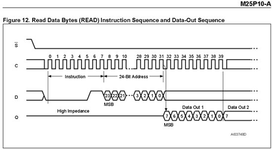
MCU is clocked from external 8MHz, eeprom connected to B0 SPI, eeprom M25p10V6 1Kbyte 25MHz SPI. can't read signature or write and then read, read returns 0xFF.
i'm burning the hex using BSL so i can't debug.
my code:
// Instructions
#define WREN 0x06 // Write Enable
#define WRDI 0x04 // Write Disable
#define RDSR 0x9F // Read Status Register
#define WRSR 0x05 // Write Status Register
#define READ 0x01 // Read Data Bytes
#define FAST_READ 0x0B // Read Data Bytes at Higher Speed
#define PP 0x03 // Page Program
#define SE 0xD8 // Sector Erase
#define BE 0xC7 // Bulk Erase
#define DP 0xB9 // Deep Power-down
#define RES 0xAB // Release from Deep Power-down, and Read Electronic Signature
#define SECTOR0_START 0x00000
#define SECTOR0_END 0x07FFF
#define SECTOR1_START 0x08000
#define SECTOR1_END 0x0FFFF
#define SECTOR2_START 0x10000
#define SECTOR2_END 0x17FFF
#define SECTOR3_START 0x18000
#define SECTOR3_END 0x1FFFF
uint16_t rx_data;
uint16_t tx_data;
uint8_t rx_int = 0;
/**
*/
void nCS(uint8_t cs) {
while ( (UCB0STAT & UCBUSY) ); // Wait While BUS Busy
if (cs) P2OUT &= ~BIT7; else P2OUT |= BIT7;
}
/**
*/
void initSPI_B0(uint8_t interrupt) {
UCSCTL4 |= SELS__XT2CLK; // SMCLK sourced from XT2
UCSCTL5 |= DIVS__8; // SMCLK divider: 8
P3SEL |= BIT0+BIT1+BIT2; // P3.0,1,2 option select
P2DIR |= BIT7; // P2.7 will be ChipSelect Pin
UCB0CTL1 |= UCSWRST; // **Put state machine in reset**
UCB0CTL0 |= UCMST+UCSYNC+/*UCCKPL+*/UCMSB; // 3-pin, 8-bit SPI master, -Clock polarity high-, MSB
UCB0CTL0 &= ~(UCCKPL + UCCKPH);
UCB0CTL1 |= UCSSEL__SMCLK; // SMCLK
UCB0BR0 = 0x02;
UCB0BR1 = 0; //
// UCB0MCTL = 0; // No modulation
UCB0CTL1 &= ~UCSWRST; // **Initialize USCI state machine**
if (interrupt) {
rx_int = interrupt;
UCB0IE |= UCRXIE; // Enable USCI_A0 RX interrupt
UCB0IE |= UCTXIE; // Enable USCI_A0 TX interrupt
}
nCS(0);
//__bis_SR_register(/*LPM0_bits + */GIE); // CPU off, enable interrupts
}
/**
*/
void spiSendByte(uint8_t data) {
while ( !(UCB0IFG & UCTXIFG) ); // USCI_A0 TX buffer ready?
UCB0TXBUF = data; // Transmit first character
while ( (UCB0STAT & UCBUSY) ); // Wait While BUS Busy
}
/*
#pragma vector=USCI_B0_VECTOR
__interrupt void USCI_B0_ISR(void)
{
volatile unsigned int i;
switch(__even_in_range(UCB0IV,4))
{
case 0: break; // Vector 0 - no interrupt
case 2: // Vector 2 - RXIFG
//while ( !(UCB0IFG & UCTXIFG) ); // USCI_A0 TX buffer ready?
if (rx_data == 0) {
rx_data = (UCB0TXBUF >> 1); // shift one bit right to get rid of first returned zero-bit
} else {
rx_data = (UCB0TXBUF << 8);
}
// do somethig with received data
nCS(0);
break;
case 4: // Vector 4 - TXIFG
break;
default: break;
}
}
*/
void eeWriteEnable() {
nCS(1);
spiSendByte(WREN);
nCS(0);
}
void eeWriteDisable() {
nCS(1);
spiSendByte(WRDI);
nCS(0);
}
// SRWD -- -- -- BP1 BP0 WEL WIP
// SRWD - status register write protect
// BPn - Block protect
// WEL - Write Enable latch bit
// WIP - write in progress bit
uint8_t eeReadStatusReg() {
nCS(1);
spiSendByte(RDSR);
nCS(0);
while ( !(UCB0IFG & UCRXIFG) ); // wait while whole byte not received
return UCB0RXBUF;
}
void eeWriteStatusReg(uint8_t reg) {
nCS(1);
spiSendByte(WRSR);
spiSendByte(reg);
nCS(0);
}
void eePollReady() {
nCS(1);
spiSendByte(RDSR);
uint8_t busy = 1;
while (busy) { // wait while busy is set
while ( !(UCB0IFG & UCRXIFG) ); // wait while whole byte not received
if( UCB0RXBUF > 0 ) busy = 1; else busy = 0; // set/clear busy
}
nCS(0);
}
uint8_t eeReadSignature() {
nCS(1);
spiSendByte(RES);
while ( !(UCB0IFG & UCRXIFG) ); // wait while whole byte not received
nCS(0);
return UCB0RXBUF;
}
void eeSleep(uint8_t s) { // 1- sleep, 0 - exit sleep
nCS(1);
if (s) spiSendByte(DP); else spiSendByte(RES);
nCS(0);
}
uint8_t eeReadByte(uint32_t addr) { // addr A24:A0 ( 3 bytes)
if (addr > SECTOR3_END) return 0;
nCS(1);
spiSendByte(READ);
spiSendByte((addr >> 16) && 0xFF);
spiSendByte((addr >> 8) && 0xFF);
spiSendByte( addr && 0xFF);
while ( !(UCB0IFG & UCRXIFG) );
nCS(0);
return UCB0RXBUF;
}
void eeReadChunk(uint32_t addr, uint8_t *data, uint8_t length) {
if ((addr + length) > SECTOR3_END) return;
nCS(1);
spiSendByte(FAST_READ);
spiSendByte((addr >> 16) && 0xFF);
spiSendByte((addr >> 8) && 0xFF);
spiSendByte( addr && 0xFF);
spiSendByte(0xFF); // dummy byte
for (uint8_t i = 0; i < length; i ++) {
while ( !(UCB0IFG & UCRXIFG) );
data[i] = UCB0RXBUF;
}
nCS(0);
}
void eeWritePage(uint32_t addr, uint8_t *data, uint8_t length) { // max is (128)256 bytes (for whole page)
if (length > 128) return;
if ((addr + length) > SECTOR3_END) return;
nCS(1);
spiSendByte(PP);
spiSendByte((addr >> 16) && 0xFF);
spiSendByte((addr >> 8) && 0xFF);
spiSendByte( addr && 0xFF);
for (uint8_t i = 0; i < length; i ++) spiSendByte(data[i]);
nCS(0);
eePollReady();
}
uint8_t eeWriteByte(uint32_t addr, uint8_t data) { // max is (128)256 bytes (for whole page)
if ((addr) > SECTOR3_END) return 1;
nCS(1);
spiSendByte(PP);
spiSendByte((addr >> 16) && 0xFF);
spiSendByte((addr >> 8) && 0xFF);
spiSendByte( addr && 0xFF);
spiSendByte(data);
nCS(0);
eePollReady();
return 0;
}
void eeSectorEraseNum(uint32_t sector) {
uint32_t sAddr = 0;
switch(sector) {
case 0:
sAddr = SECTOR0_START;
break;
case 1:
sAddr = SECTOR1_START;
break;
case 2:
sAddr = SECTOR2_START;
break;
case 3:
sAddr = SECTOR3_START;
break;
default:
break;
}
nCS(1);
spiSendByte(SE);
spiSendByte((sAddr >> 16) && 0xFF);
spiSendByte((sAddr >> 8) && 0xFF);
spiSendByte( sAddr && 0xFF);
nCS(0);
eePollReady();
}
void eeBulkErase() {
nCS(1);
spiSendByte(BE);
nCS(0);
eePollReady();
}
in main function:
initSPI_B0(0);
uint8_t eeReg = eeReadSignature();
if (eeReg > 0) {P2OUT &= ~BIT1;}
eeWriteEnable();
uint8_t data[5];
data[0] = 0x06;
eeWriteByte(0x00001, data[0]); //eeWritePage(0x000001, data, 1);
eeWriteDisable();
__delay_cycles(4000000);
uint8_t rc = eeReadByte(0x00001);
if (data[0] == rc) P2OUT &= ~BIT0;
if (rc == 0xFF) rc = 0;
for (uint8_t i = 0; i < rc; i ++) {
__delay_cycles(4000000);
P2OUT ^= BIT3;
__delay_cycles(4000000);
P2OUT ^= BIT3;


