This thread has been locked.

If you have a related question, please click the "Ask a related question" button in the top right corner. The newly created question will be automatically linked to this question.

Timer A as freq counter rare error ... race condition on overflows?

I thought I had this resolved here before but ran into a rare error.

Here is the basic operation:

1.  I am using Timer A to capture a square wave input on P1.1. Timer A is in cont mode and the signal input range I am needing is 0Hz to 3KHz.

2.  I keep track of the edges triggering the Timer A0  int.  My input signal source I am not gauranted a 50/50 duty cycle so I capture on the rising edges. 2 rising edges get me one full period.

3.  I capture the first edge, grab the timer TACCR0 and put into "startcount", I grab the next edge TACCR0 and put into "stop count" This always works.

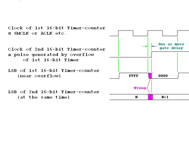
4.  Since I am running Timer A continuously and my clock is high (for precision) then in order to extend the range of the freq counter I keep track of the Timer A overflows.

5.  With the Timer A going continuously I do a test in the TIMER A0 INT and see if "startcount" is less than "stopcount" or if it greater than.

6.  If startcount is greater than stopcount then I substract 1 overflow from the total. This usually works.

     If startcount is less than stopcount then no correction to the overflows total. This usually works.

7. The overflows are increased in the Timer A1 INT.

8. In my main loop then my final freq is the total of overflows accumlated plus the "startcount - stopcount" amount.

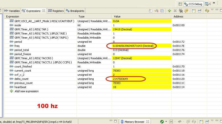
9. I set a breakpoint in the main loop after I calculate my freq to check accuracy. On rare occasions the overflow is 1 too high if  startcount < stopcount. On rare occasions the overflow is 1 too low if  startcount > stopcount.  WHen I use the breakpoint then I keep the input freq. fixed. In this example I keep at 500 Hz.

10. Frequency is then output on the COM port and fed to a PC terminal. (this works). The freq error is so rare I have yet to see it on the COM output, however I only output once every second.

I have other features in the pgm but not related to the freq calculate problem, for reference I highlighted the critcal and relavent code bold red.

MAIN CODE

//******************************************************************************
//   MSP430x26x  - USCI_A0, 115200 UART Echo ISR,
//
//   Description: Echo a received character, RX ISR used.
//   USCI_A0 RX interrupt triggers TX Echo.
//   Baud rate divider with 1MHz = 1MHz/115200 = ~8.7
//   Using External Clock = 10MHz
//  Start and Stop timers, enable/disable Port 1 int, and Set Modes Variables based on numbers from COMM RX ISR
//  Generate Pulses on P4.0 output based on Input P1.1 activity
//
//             MSP430F261x/241x
//             -----------------
//         /|\|              XIN|------------->
//          | |                 |10 MHz ext clock
//          --|RST          XOUT|-<------------
//            |                 |
//     |            P1.1 | Timer_A3.CCIOA Input. Int on rising edge
//            |     P3.4/UCA0TXD|------------>
//            |                 | 115200 - 8N1
//            |     P3.5/UCA0RXD|<------------
//            |                 |
//            |           P4.0  | Output. Default low
//******************************************************************************
/*
 * ======== Standard MSP430 includes ========
 */
#include <msp430.h>
#include <stdio.h>
#include <string.h>

/*
 * ======== Grace related declaration ========
 */
extern void CSL_init(void);

int mode;   // based on rcv character, used to set which variable to output on 1Hz "heartbeat"
int rxdata; // rcv char over comm
extern volatile unsigned int period; //
extern volatile unsigned int period_freeze; //
double overflow_time;//
double clockrate;// 10 MHz clock
extern double freq; // FRAW frequency!!!!!
extern volatile double period_total;//
extern unsigned long leading_edges;
extern volatile unsigned int ta_overflows;
extern volatile unsigned int ta_overflow_end;
extern volatile unsigned int ta_overflows_start;//
extern volatile unsigned int ta_overflows_stop;//
extern volatile unsigned int ta_overflow_total;// Used for total ticks tally so that < 153 Hz can be measured
extern volatile int heartbeat; //Software counter variable based on Timer A overflow ... Sets 1 Hz txdata out rate
extern volatile unsigned int startcount;// First leading edge
extern volatile unsigned int stopcount; // 2nd leading

double period_total_freeze;

extern volatile int count_finished;

extern volatile unsigned int fault;

unsigned int periodB; //
float DegC;//
char freq_strg[40];

unsigned char n_avg;
double freq_avg;
double tempdbl_freq;
double tempdb2_freq;
const double taovr = 0.0065535;

/* This works but must know length
void sendstring(char * str, int len)
  {
  int i = 0;
  for(i = 0; i < len; i++)
  {
  while (!(IFG2 & UCA0TXIFG)); // USART0 TX buffer ready?
  UCA0TXBUF = str[i];
  mode=9;
  }
 }
 */

void sendstring(char * str)// Used to send TX data out as string when 1Hz has elapsed from Timer A "heartbeat" ticks captured in software counter
  {
  int i = 0;
  for(i = 0; i < strlen(str); i++)
  {
   while (!(IFG2 & UCA0TXIFG)); // USART0 TX buffer ready?
   UCA0TXBUF = str[i];
  }
 }

/*
 *  ======== main ========
 */

main(void)
  {
WDTCTL = WDTPW + WDTHOLD;                 // Stop WDT


CSL_init();                     // Activate Grace-generated configuration

P4DIR |= 0x01;                            // Set P1.0 to output direction
P4SEL |= 0x01;


TBCCR0 = 1000-1;
TBCTL = TBCLGRP_0 + CNTL_0 + TBSSEL_2 + ID_0 + MC_1;                  // SMCLK, upmode


TBCCTL0 = CM_0 + CCIS_0 + SCS + CLLD_1 + OUTMOD_4 + OUT + TBCLR;

_BIS_SR(GIE);  // Allow interrupts

overflow_time= 0.0065535; // full timer A elapsed time after overflow 65535 x 0.0000001 (10 MHz clock)
// Initialize all the variables
mode = 1;
rxdata = 1;
leading_edges = 0;
ta_overflows=0;
startcount=0;
stopcount=0;
count_finished = 0;
ta_overflows_start = 0;
ta_overflows_stop = 0;
period = 0;
freq = 0;
clockrate = 0.0000001; // 10 MHz clock
ta_overflow_total = 0; // initializes timer A overflow counts
n_avg = 1;

TBCCR0 = 1000-1;
    while (1) {
               // Scan COM for mode change

           if (rxdata == 1) {
            // If rxdata = 1 then mode = 1
                 mode = 1;
              }
           if (rxdata == 2) {
            // If rxdata = 2 then mode = 2
              mode = 2;
              }
           if (rxdata == 3) {
              // If rxdata = 3 then mode = 3
              mode = 3;
              }
           if (rxdata == 4) {
              // If rxdata = 4 then mode = 4
              mode = 4;
              }
           if (rxdata == 5) {
              // If rxdata = 5 then mode = 5
              mode = 5;
              }
           if (rxdata == 6) {
              // If rxdata = 6 then mode = 6
              mode = 6;
              }
           if (rxdata == 7) {
              // If rxdata = 7 then mode = 7
              mode = 7;
              }
           if (rxdata == 8) {
              // If rxdata = 8 then mode = 8
              mode = 8;
              }
           if (rxdata == 9) {
              // If rxdata = 9 then mode = 9
              mode = 9;
              }

           if (heartbeat == 152){
            heartbeat = 0;

            //sprintf(freq_strg, "FRAW Frequency = %04.4f Hz\r\n",freq);
               sprintf(freq_strg, "FRAW Frequency = %04.4f Hz\r\n",freq_avg);
               sendstring(freq_strg);         //string output
               }

           if (count_finished == 1){

              period_total= (taovr * ta_overflow_end) + (period_freeze * 0.0000001);
              freq= 1/period_total; // mgp

                    if ((freq > 500.5) || (freq < 499.5)){

 MY BREAKPOINT IS HERE      mode = 9; // Stop if freq out of limits.  the error is always "ta_overflow_end" error and always from the Timer A  INT               

                    }


                  // If single period average, use current input as average
                    if (n_avg == 1)
                   freq_avg = freq;
                   else         // Else, using rolling average formula
                      {
                      tempdbl_freq = n_avg-1; // f_avg = ((n_avg-1)*f_avg+fin)/n_avg
                      tempdb2_freq = tempdbl_freq * freq; // Simplified to reduce temps
                      tempdbl_freq = tempdb2_freq + freq;
                      freq_avg = tempdbl_freq/n_avg;
                          //mode = 9; // I use this only for debug purposes setting break point
                      }


                 if (freq_avg >= 153){
                  TBCTL = TBCLGRP_0 + CNTL_0 + TBSSEL_2 + ID_1 + MC_1;
                        periodB = (1/freq_avg)/(.0000004);
                        TBCCR0 = periodB;
                        //mode = 9; // MGP I use this only for debug purposes setting break point here
                        }

             period = 0;
             period_total = 0;
             count_finished = 0;
             }
// mode = 9; // MGP I use this only for debug purposes setting break point here
   }
}

void USCI0RX_ISR(void)
{
    while (!(IFG2&UCA0TXIFG));                // USCI_A0 TX buffer ready?
    rxdata = UCA0RXBUF;
    UCA0TXBUF = UCA0RXBUF;                    // TX -> RXed character
}

// Timer B0 interrupt service routine
#pragma vector=TIMERB0_VECTOR
__interrupt void Timer_B (void)
{

}

TIMER A INIT CODE (from Grace)

void Timer_A3_graceInit(void)
{
    /* USER CODE START (section: Timer_A3_graceInit_prologue) */
    /* User initialization code */
    /* USER CODE END (section: Timer_A3_graceInit_prologue) */
   
    /*
     * TACCTL0, Capture/Compare Control Register 0
     *
     * CM_1 -- Rising Edge
     * CCIS_0 -- CCIxA
     * SCS -- Sychronous Capture
     * ~SCCI -- Latched capture signal (read)
     * CAP -- Capture mode
     * OUTMOD_0 -- PWM output mode: 0 - OUT bit value
     *
     * Note: ~SCCI indicates that SCCI has value zero
     */
    TACCTL0 = CM_1 + CCIS_0 + SCS + SCCI + CAP + OUTMOD_0 + CCIE;

    /*
     * TACTL, Timer_A3 Control Register
     *
     * TASSEL_2 -- SMCLK
     * ID_0 -- Divider - /1
     * MC_2 -- Continuous Mode
     */
    TACTL = TASSEL_2 + ID_0 + MC_2 + TAIE;

    /* USER CODE START (section: Timer_A3_graceInit_epilogue) */
    /* User code */
    /* USER CODE END (section: Timer_A3_graceInit_epilogue) */


TIMER A INT CODE (in Grace generated file)

/*
 *  ======== Timer_A3 Interrupt Service Routine ========
 */
#pragma vector=TIMERA0_VECTOR
__interrupt void TIMERA0_ISR_HOOK(void)
{
    /* USER CODE START (section: TIMERA0_ISR_HOOK) */
 count_finished = 0;
 leading_edges ++;
 fault = 0;


 switch (leading_edges)
 {
    case  1:
     ta_overflows_start = ta_overflows;
  startcount = TACCR0;
  fault = 1;
  break;
 case 2:
  ta_overflows_stop = ta_overflows;
  stopcount = TACCR0;
  period = stopcount - startcount; //MGP
  period_freeze = period;
  ta_overflow_total = ta_overflows_stop - ta_overflows_start;
  fault = 2;

  if(startcount > stopcount){
    ta_overflow_end = ta_overflow_total - 1;//   Sometime this fails -  may be 1 too high!
    leading_edges = 0;
    count_finished = 1;
    fault = 3;
  }

  if(startcount < stopcount){
    ta_overflow_end = ta_overflow_total + 0; // Sometime this fails -  may be 1 too low!! 

leading_edges = 0;
    count_finished = 1;
    fault = 4;
  }
  break;


 }

}
    //* USER CODE END (section: TIMERA0_ISR_HOOK) */
/*
 *  ======== Timer_A3 Interrupt Service Routine ========
 */
#pragma vector=TIMERA1_VECTOR
__interrupt void TIMERA1_ISR_HOOK(void)
{
    /* USER CODE START (section: TIMERA1_ISR_HOOK) */
    /* replace this comment with your code */
 if (count_finished == 0) ta_overflows ++;
 heartbeat ++;
 TACTL &= ~TAIFG;
    /* USER CODE END (section: TIMERA1_ISR_HOOK) */
}
/*
 * ======== Preserved user code snippets ========
 */
#if 0
    /* USER CODE START (section: TIMERB0_ISR_HOOK) */
// TBCTL &= ~TBIFG;
//P4OUT ^= 0x01;  // Toggle P4.0 using exclusive-OR - MGP added
    /* USER CODE END (section: TIMERB0_ISR_HOOK) */
#endif


}

  • I have an algorithm to capture a 31-bit period (delta_count) with a 16-bit Timer.

    1. Define global variables.

       static volatile U16 ovf_x_2;
       static volatile U32 current_count;
       static volatile U32 previous_count;
       static volatile U32 delta_count;

    2. Configure the Timer and an input pin.

       Use CC0 to interrupt and capture input edge.
       Use CC1 to interrupt on compare with 0x8000.
       Use this Timer to interrupt on overflow in continouse counting mode.

    3. ovf_x_2 is incremented by both the CC1 and the Timer overflow ISR.
       As a result, it becomes an odd number after each CC1 interrupt.
       And it becomes an even number after each Timer overflow interrupt.

    4. The CC0 ISR does the following.

       if (CCR0 < 0x4000)
         current_count = (U32)((ovf_x_2 + 1) & 0xFFFE) << 15 + CCR0;
       else
         current_count = (U32)(ovf_x_2 & 0xFFFE) << 15 + CCR0;

       delta_count = current_count – previous_count;

           previous_count = current_count;

  • Michael Parrish said:
     if(startcount > stopcount){
        ta_overflow_end = ta_overflow_total - 1;//   Sometime this fails -  may be 1 too high!


    Since both counts are unsigned ints, the previous subtraction will always be positive, even if it should be a negatove value. As a result, you have the addition ot 65536 by the falsely positive difference, and also teh overflow that caused it. A possible solution would be to make a signed long subtraction:

    signed long perod = (signed long)stopcount - (signed long)startcount;

    The result will be negative when there was an overflow between the two but the stop count didn't reach the start count, so it was an incomplete cycle. The total number of counts then is

    signed long period = (overflows<<16)|((signed long)stopcount - (signed long)startcount);

  • Michael,

    You are correct in saying that there is a racing condition between timer overflow and timer capture. CCR0 hardware captures the 16-bit count, this CCR0 captured count can be read by your code later. The overflow count is not updated by hardware directly. It is updated later by timer overflow ISR and can be read by your code elsewhere. The racing condition happens only when the CCR0 captured count is very small (i.e., the capturing happens very shortly after timer overflows). That is why it happens very rarely.

    I think the algorithm used in your code to resolve this race condition is incorrect. It has nothing to do with whether startcount is less than stopcount or not. The race condition happens only when (a) startcount is very small, (b) stopcount is very small, or (c) both. If and when the race condition happens, your code is not able to resolve it.

    -- OCY

  • Correction.

    The race condition can also happen when the CCR0 captured count is very big (i.e. the capturing happens very shortly before timer overflows)

    The algorithm I sent you earlier should be able to resolve both situations -- very small and very big.

    -- OCY

  • Thank you for responding, your approach makes sense, just I cannot understand beyond your concept enough to code this properely.

    I have some questions about the psudo-code you provided, so I made mark-ups in your quote text body.  Also, below I posted my code, I know I am way off, but anyway it compiles and is a starting point for your implimentation

    old_cow_yellow said:

    I have an algorithm to capture a 31-bit period (delta_count) with a 16-bit Timer.

    1. Define global variables.

       static volatile U16 ovf_x_2;
       static volatile U32 current_count;
       static volatile U32 previous_count;
       static volatile U32 delta_count;

    Comment: CCS Compiler won't allow this ... error is "more than one storage class may not be defined". So I only used "volatile", I didn't try using "static" only. Must be either "volatile" or "static", not both.


    2. Configure the Timer and an input pin.

       Use CC0 to interrupt and capture input edge.

       Use CC1 to interrupt on compare with 0x8000.

    Comment: Should this be a timer hardware config (INIT) on CC1, or do I do this in the TIMERA1_VECTOR INT in software as I have pasted in my code below? What do I do after I compare? In my code I incremented ovf_x_2?

       Use this Timer to interrupt on overflow in continouse counting mode.

    3. ovf_x_2 is incremented by both the CC1 and the Timer overflow ISR.
       As a result, it becomes an odd number after each CC1 interrupt.
       And it becomes an even number after each Timer overflow interrupt.

    4. The CC0 ISR does the following.

       if (CCR0 < 0x4000)
         current_count = (U32)((ovf_x_2 + 1) & 0xFFFE) << 15 + CCR0;

    Comment: "(U32)" is this supposed to be part of the code? I have already assigned ovf_x_2 as a "U16".

       else

         current_count = (U32)(ovf_x_2 & 0xFFFE) << 15 + CCR0;

       delta_count = current_count – previous_count;

    Comment: On the first pass through (after firmware start) this "previous_count" is not established, default is zero. If "previous count" is really my starting count, then it seems to be only valid once I pass thrupugh the very first INT 1 time.  The first pass after CPU startup seems not valid.

    Before I would keep track of whether there was a first rising edge, grab the count in TACCR0, assign it to "startcount", then on the second leading edge I would grab the count in TACCR0 and assign it to "stopcount". Not clear to me how this is accomplished now. 

    I assume I will be picking up "delta_count" in my main loop and it should contain the start and stop captures + the legitimate overflows only, not the ones created by the race problem?

           previous_count = current_count;

    Here is my code I used, Only thing I am doing to test this now is to set a breakpoint in the main loop then check values in the ISR's.  Previous count, current count, ovf_x_2, and delta count are always zero. 

    MAIN

    extern volatile int heartbeat; //Software counter variable based on Timer A overflow ... Sets 1 Hz txdata out rate
    extern volatile int count_finished;  //Wait for input freq calc in the INT to be completed before further processing
    extern volatile unsigned int ovf_x_2;
    extern volatile unsigned long current_count;
    extern volatile unsigned long previous_count;
    extern volatile unsigned long delta_count;


    etc

    if (count_finished == 1){

            //period_total= (taovr * ta_overflow_end) + (period_freeze * 0.0000001);
    BREAKPOINT HERE        freq= 1/period_total; // mgp

    etc etc


    INT Code (external file from grace)


    #include <msp430.h>

    /* USER CODE START (section: InterruptVectors_init_c_prologue) */
    /* User defined includes, defines, global variables and functions */

    volatile int heartbeat;
    volatile int count_finished;
    volatile unsigned int ovf_x_2;
    volatile unsigned long current_count;
    volatile unsigned long previous_count;
    volatile unsigned long delta_count;


    #pragma vector=TIMERA0_VECTOR
    __interrupt void TIMERA0_ISR_HOOK(void)
    {

           if (TACCR0 < 0x4000){
             current_count = ((ovf_x_2 + 1) & 0xFFFE) << 15 + TACCR0;
           }
           else {
             current_count = (ovf_x_2 & 0xFFFE) << 15 + TACCR0;
             delta_count = current_count - previous_count;
             previous_count = current_count;
             count_finished = 1;
           }

        /* USER CODE END (section: TIMERA0_ISR_HOOK) */
    }

    /*
     *  ======== Timer_A3 Interrupt Service Routine ========
     */
    #pragma vector=TIMERA1_VECTOR
    __interrupt void TIMERA1_ISR_HOOK(void)
    {
        /* USER CODE START (section: TIMERA1_ISR_HOOK) */
        /* replace this comment with your code */
     if (TACCR0 < 0x8000){
     ovf_x_2 ++;
     }
     TACTL &= ~TAIFG;
     heartbeat ++;
        /* USER CODE END (section: TIMERA1_ISR_HOOK) */
    }


    Timer A3 init (external from Grace)

    void Timer_A3_graceInit(void)
    {
        /* USER CODE START (section: Timer_A3_graceInit_prologue) */
        /* User initialization code */
        /* USER CODE END (section: Timer_A3_graceInit_prologue) */
       
        /*
         * TACCTL0, Capture/Compare Control Register 0
         *
         * CM_1 -- Rising Edge
         * CCIS_0 -- CCIxA
         * SCS -- Sychronous Capture
         * ~SCCI -- Latched capture signal (read)
         * CAP -- Capture mode
         * OUTMOD_0 -- PWM output mode: 0 - OUT bit value
         *
         * Note: ~SCCI indicates that SCCI has value zero
         */
        TACCTL0 = CM_1 + CCIS_0 + SCS + CAP + OUTMOD_0 + CCIE;

        /*
         * TACTL, Timer_A3 Control Register
         *
         * TASSEL_2 -- SMCLK
         * ID_0 -- Divider - /1
         * MC_2 -- Continuous Mode
         */
        TACTL = TASSEL_2 + ID_0 + MC_2 + TAIE;

        /* USER CODE START (section: Timer_A3_graceInit_epilogue) */
        /* User code */
        /* USER CODE END (section: Timer_A3_graceInit_epilogue) */
    }

  • old_cow_yellow said:
    I think the algorithm used in your code to resolve this race condition is incorrect. It has nothing to do with whether startcount is less than stopcount or not.

    Right. This correction compensates for an overflow counted when there is no complete cycle. Which is correct in most cases but can be eliminated by using the signed math I proposed.
    However, my proposal doesn't eliminate the occasional racing condition. This can be done otherwise:
    Both, the capture and the overflow, trigger an ISR. Since the overflow (not the TAIE, but the CCR0.CCIE) has its own ISR and its own ISR and higher priority, it will be called first - unless the capture happened before (even shortly) the overflow.
    This requires that GIE is set all the time (that means, no other ISRs executing). because if GIE is clear while overflow and capture happen, then the overflow will always be handled first even if it happened second.

  • old_cow_yellow said:

    I think the algorithm used in your code to resolve this race condition is incorrect. It has nothing to do with whether startcount is less than stopcount or not. The race condition happens only when (a) startcount is very small, (b) stopcount is very small, or (c) both. If and when the race condition happens, your code is not able to resolve it.

    -- OCY

    Thx.

    My code wasn't trying to eliminate the race condition .. I wasn't even aware of that problem initially. The reason for the "test" to see if the startcount was less than or greater than the stopcount was due to the input signal not having any syncronization to where the timer used for start or stop count was in it's count initially when the first edge appears.

    For example if the incoming edge to edge was 20000 "clock ticks" and the counter was at 60000 then there would always be an overflow. If the edge to edge count was 20000 "clock ticks" then there would not be an overflow.  If the startcount was greater than stopcount then that means there would always be one extra overflow. Other overflows (meaning the incoming signal freq was larger than the timer capacity) would get counted.

    I was doing 2 seperate calculations, one for total overflows, one for startcount/stopcount duration, then combining those in the main loop to get my total.

    Anyway I need some help on understanding how your method works and appreciate your input.


  • Jens-Michael Gross said:

     if(startcount > stopcount){
        ta_overflow_end = ta_overflow_total - 1;//   Sometime this fails -  may be 1 too high!


    Since both counts are unsigned ints, the previous subtraction will always be positive, even if it should be a negatove value. As a result, you have the addition ot 65536 by the falsely positive difference, and also teh overflow that caused it. A possible solution would be to make a signed long subtraction:

    signed long perod = (signed long)startcount - (signed long)startcount;

    The result will be negative when there was an overflow ibetween the two but the stop count didn't reach the start count, so it was an incomplete cycle. The total number of counts then is

    signed long period = (overflows<<16)|((signed long)startcount - (signed long)startcount);

    [/quote]

    Thx. You have startcount being substracted from startcount ... this would always be zero. Is there a typo perhaps and one should be stopcount and the other stratcount?

  • Michael Parrish said:
    Is there a typo perhaps and one should be stopcount and the other stratcount?

    Right. Silly typo. Of yourse it must be stopcount-startcount. I'll fix that in my post :)
    The result is negative, n*65536 lower than it should be, if there were n overflows between start and stop. Which is compensated by adding n*65536 for the counted overflows.

  • Jens-Michael Gross said:

    I think the algorithm used in your code to resolve this race condition is incorrect. It has nothing to do with whether startcount is less than stopcount or not.

    Right. This correction compensates for an overflow counted when there is no complete cycle. Which is correct in most cases but can be eliminated by using the signed math I proposed.
    However, my proposal doesn't eliminate the occasional racing condition. This can be done otherwise:
    Both, the capture and the overflow, trigger an ISR. Since the overflow (not the TAIE, but the CCR0.CCIE) has its own ISR and its own ISR and higher priority, it will be called first - unless the capture happened before (even shortly) the overflow.
    This requires that GIE is set all the time (that means, no other ISRs executing). because if GIE is clear while overflow and capture happen, then the overflow will always be handled first even if it happened second.

    [/quote]


    OCY or Jens, or anyone ...

    I'm still very lost and confused on this.  I took OCW pseudo-code below 

    ************************************************************

    I have an algorithm to capture a 31-bit period (delta_count) with a 16-bit Timer.

    1. Define global variables.

       static volatile U16 ovf_x_2;
       static volatile U32 current_count;
       static volatile U32 previous_count;
       static volatile U32 delta_count;

    2. Configure the Timer and an input pin.

       Use CC0 to interrupt and capture input edge.
       Use CC1 to interrupt on compare with 0x8000.
       Use this Timer to interrupt on overflow in continouse counting mode.

    3. ovf_x_2 is incremented by both the CC1 and the Timer overflow ISR.
       As a result, it becomes an odd number after each CC1 interrupt.
       And it becomes an even number after each Timer overflow interrupt.

    4. The CC0 ISR does the following.

       if (CCR0 < 0x4000)
         current_count = (U32)((ovf_x_2 + 1) & 0xFFFE) << 15 + CCR0;
       else
         current_count = (U32)(ovf_x_2 & 0xFFFE) << 15 + CCR0;

       delta_count = current_count – previous_count;

           previous_count = current_count;

    *****************************************************

    Then came up with this.

    For the Timer Interupts ....

    #pragma vector=TIMERA0_VECTOR
    __interrupt void TIMERA0_ISR_HOOK(void)
    {

     if (TACCR0 < 0x4000)
          current_count = ((ovf_x_2 + 1) & 0xFFFE)<< 15 + TACCR0;
        else
         current_count = (ovf_x_2 & 0xFFFE) << 15 + TACCR0;
            delta_count = current_count - previous_count;
            previous_count = current_count;

    }

    /*
     *  ======== Timer_A3 Interrupt Service Routine ========
     */
    #pragma vector=TIMERA1_VECTOR
    __interrupt void TIMERA1_ISR_HOOK(void)
    {
        /* USER CODE START (section: TIMERA1_ISR_HOOK) */
        /* replace this comment with your code */
     ovf_x_2 ++;
     TACTL &= ~TAIFG;
     heartbeat ++;  // This is for 1 sec output rate on COM used in main loop. Output freq on COM once a second
     /* USER CODE END (section: TIMERA1_ISR_HOOK) */
    }

    Timers INIT

    TACCR1 = 0x8000; // Use this for Compare value on CCR1?
    TACTL = TASSEL_2 + ID_0 + MC_2 + TAIE;
    TACCTL0 = CM_1 + CCIS_0 + SCS + CAP + OUTMOD_0 + CCIE;  // Capture rising edges on P1.1 CCIxA = CCIS_0
    TACCTL1 = CM_0 + CCIS_0 + SCS + OUTMOD_0; //  Use CCR1 for compare?

    _BIS_SR(GIE);

    Variables in Main

    volatile unsigned int ovf_x_2;
    volatile unsigned long current_count;
    volatile unsigned long previous_count;
    volatile unsigned long delta_count;

    ************************************

    I plan on just grabbing "delta_count " in my main loop then just calculate my freq based on that value.  The capture appears to be working as when I debug then if I have signal on P1.1 then delta_count, current_count, previous_count, and ovf_x_2, and all are reporting numbers in debug ... if I remove the input signal no numbers are reporting. 

    The use of TACCR1 I only find code examples for things like PWM etc.  If I understand everything correctly the CCR0 is where I capture rising edges and CCR1 is where the overflows are caught and it's setup is to set TACCR1 to 0x8000 for capture. I'm sure the init I have on the timers is really goofball.  Delta_count has "running" values but when I put a constant freq in the input on P1.1 this doesn't seem to give be a stable value, even with the input fixed a one freq.

    I suppose most people either gang (2) 16 bit timers together or use the "D" timer on other MSP430 devices when they want to measure a wide range of input freq. but I am stuck with this device as it is a high temp part ( -55 - +150 C) so I really need to get a handle on this ... use a single 16 bit timer A and capture close to 0 Hz and up to 3K. My timer B has to be used for generating an output freq. So I can't gang the timers.

    Any help is well appreciated, I do try and figure things out on my own and look for examples and read the docs, just doesn't seem many people are trying to do this on a single 16 bit timer.  This thing is killing me yikes!!!


  • Sorry, I cannot help you. I do not know how to use c. I know nothing about CCS or Grace. Here is my blind attempt, it might not compile, and it might not work.

    #include <msp430.h>

    #define U16 unsigned int

    #define U32 unsigned long


    volatile U16 ovf_x_2;

    volatile U32 current_count;

    volatile U32 previous_count;

    volatile U32 delta_count;


    void main (void)

    {

      WDTCTL = WDTPW | WDTHOLD;

      P1SEL = BIT1; //??? P1.1 as Timer CC0 input ???

      //??? set up MCLK & SMCLK ???

      TACCR1 = 0x8000;

      TACCTL0 = CM_1 | SCS | CAP | CCIE;

      TACCTL1 = CCIE;

      TACTL = TASSEL_2 | MC_2 + TAIE;


      __bis_SR_register(GIE);

      while (1) { /* Do nothing */ }

    }


    #pragma vector=TIMERA0_VECTOR

    __interrupt void TIMERA0_ISR(void)

    {

      if (CCR0 < 0x4000)

        current_count = ((U32)((ovf_x_2 + 1) & 0xFFFE) << 15) + CCR0;

      else

        current_count = ((U32)(ovf_x_2 & 0xFFFE) << 15) + CCR0;


      delta_count = current_count - previous_count;

      previous_count = current_count;

    }


    #pragma vector=TIMERA1_VECTOR

    __interrupt void TIMERA1_ISR(void)

    {

      if (TACTL & TAIFG)

      {

        TACTL &= ~TAIFG;

        ovf_x_2++;

      }

      if (TACCTL1 & CCIFG)

      {

        TACCTL1 &= ~CCIFG;

        ovf_x_2++;

      }

    }


    I do not how the Debugger works either. But I think if you set any breakpoint in the above code, the Timer would not count correctly. I think the following might work.

    (a) Do not set any break and let the code run.

    (b) After at least two rising edges at P1.1, manually break it.

    (c) Inspect delta_count, it should contain the # of counts between the latest two rising edges.


  • Michael Parrish said:
    I suppose most people either gang (2) 16 bit timers together or use the "D" timer on other MSP430 devices when they want to measure a wide range of input freq.

    Indeed, you can let one timer generate a puls eon overflow that is taken as clock into to a second timer, giving you a prefect 32 bit timer.

    However, there' sanother option: if you detect a frequency that is near the current upper or lower limit for a single cycle, change the timer clock yb a factor of two. With the SMCLK divider and the timer divider, this gives you soem additional decades of detection range. At the expense of one missing/invalid value (at least it is knwo which value is affected) or some additional calculation overhead to reconstruct it across the clock speed change.

  • Jens-Michael Gross said:
    ... Indeed, you can let one timer generate a puls eon overflow that is taken as clock into to a second timer, giving you a prefect 32 bit timer. ...

    The leading edge of the the overflow pulse will not align perfectly with  the clock of that timer. (There will be one or more gate delays.)  Thus the two 16-bit timers cannot be regarded as a perfect 32-bit time. (; There is still a race, but a very closer one ;)

  • Clarification.

  • Here is my idea of using two 16-bit Timer-counters as a near perfect single 31-bit counter. (; I am confident that I am sane and of sound mind ;)

    Set up one 16-bit Timer-counter, call it x, to capture begin and end of an event. Use SMCLK or ACLK in continues-mode from 0000 to FFFF.

    U16 start_count_x;

    U16 end_count_x;

    U16 delta_count_x;

    delta_count_x = end_count_x – start_count_x;

    Set up another 16-bit Timer-counter, call it y, to capture begin and end of the same event. Use the same SMCLK or ACLK but in up-mode from 0000 to FFFE instead.

    U16 start_count_y;

    U16 end_count_y;

    U16 delta_count_y;

    if (end_count_y > start_count_y)

        delta_count_y = end_count_y – start_count_y;

    else

        delta_count_y = 0xFFFF + end_count_y – start_count_y;

    From the above two 16-bit counters x and y, a single 31-bit big counter can be constructed as:

    (U32) delta_count_big;

    delta_count_big = (U32) delta_count_y  +

             0xFFFF * (U32)(delta_count_y – delta_count_x);

    (Let the compiler optimize this calculation.)

  • OCY said:
    Clarification.

    Yes, you're right. If the trigger event happens during this small delay of a few ns, it might happen that the overflow isn't counted. Well, this window is, as you said, much smaller (by several magnitudes) than anything you could do in software.

    Anotehr idea is to run both timers from SMCLK, but with different dividers (minimum for one, maximum for the other). Then the problem vanishes. However, the gain in additional bits is only as large as the difference in the clock divider, so not 32 bit. Still a big step forward.

  • JMG,

    Please scrutinize "Here is my idea of using two 16-bit Timer-counters as a near perfect single 31-bit counter."

    Thanks,

    -- OCY

  • old_cow_yellow said:
    Here is my idea of using two 16-bit Timer-counters as a near perfect single 31-bit counter. (; I am confident that I am sane and of sound mind ;)

    old_cow_yellow, you are perfectly sane ;-)

    Your idea encouraged me to do some math, and it seems that you have a near 32-bit counter (from 0 to 0xFFFF0000 - 1). You can not only capture hardware events, you can also read the X and Y timers in software and calculate large time differences, provided that the delay between reading X and Y from the hardware registers is always the same (interrupts disabled between reads and no DMA active should allow this on such a simple and nice architecture as MSP430).

    There may be one simple correction needed in the final calculation. The final result may be negative and needs to be folded to the 0..(0xFFFF0000-1) interval by adding 0xFFFF0000 when delta_count_y < delta_count_x.

  • old_cow_yellow said:
    Please scrutinize "Here is my idea of using two 16-bit Timer-counters as a near perfect single 31-bit counter."

    Hmmm, looks like an excellent idea to determine the number of overflows in an interval by the drift of the second counter. If both counters capture at the same moment (synchronized to their common clock), it indeed should work fine.

  • Michal and JMG,

    Thanks for reading and commenting on this method.

    Yes, it is subject to the limitations you two pointed out. But I think the simple correction Michal said is not needed. An (U16) or (U32) expression will never be negative

    -- OCY.


  • Indeed. I was considering a bit too general case (two arbitrary periods). Here the 16-bit subtraction and 32-bit promotion does the trick.

  • old_cow_yellow said:

    Sorry, I cannot help you. I do not know how to use c. I know nothing about CCS or Grace. Here is my blind attempt, it might not compile, and it might not work.

    (OCW CODE EXCLUDED FOR BREVITY)

    I do not how the Debugger works either. But I think if you set any breakpoint in the above code, the Timer would not count correctly. I think the following might work.

    (a) Do not set any break and let the code run.

    (b) After at least two rising edges at P1.1, manually break it.

    (c) Inspect delta_count, it should contain the # of counts between the latest two rising edges.


    Hello OCW.  Your code pretty much works Verbatim.

    There are a couple of anomalies, but overall this is far better than what I had before.  Both errors are very rare.

    One of the  anomalies the freq will be reported as an impossible freq value. I keep the input at a fixed freq and then monitor in my main loop for +/-  .1% of the generator input freq.

    I then "trap" using a breakpoint in debug mode. This error was happening maybe  once every 2 hours or so, but never really exactly every 2 hours. When it does happen the symptoms are the same no matter what freq is used. I took a screen grab when I trapped at both 100 hz and then 10 Hz input.

     As you can see the freq is .00465 hz and the Delta_Counts is huge. In both these screens the numbers in the errors are nearly the same.  I'm not understanding why this is happening, but since the error is repeatable and and the delta count "impossible" I am able to filter it out in the main loop and discard whenever freq (via delta_count)  is below my low end cutoff I set.  My actual application I don't need to go to zero, anything below 2 Hz I can "throw-away".


    The other error is even more rare, I ran all weekend and only had 2 of these error occurances happen.  This was a "trap" setting a breakpoint in debug when I captured this screen below.

    For my weekend test when I got the 2 errors I just setup a varible to increment whenever the 100 Hz +/- .1 % was exceeded and let it continue running on failure, I need to figure how to identify if possible that this is not a valid freq, however, in these cases the error was in a valid freq range, so I need to look at in more detail.  I haven't ruled out that perhaps some noise on my input was presented and not a software issue, but I am using a very stable Agilent function generator, but I'm keeping an open mind on my second error.

    If any insight into this would be greatly appreciated.


    My relevent code is ...


    Main

    Defines and variables ...

    #define U16 unsigned int

    #define U32 unsigned long


    volatile U16 ovf_x_2;

    volatile U32 current_count;

    volatile U32 previous_count;

    volatile U32 delta_count;


    Initialization (in main) ...

    TACCR1 = 0x8000;

    TACCTL0 = CM_1 + SCS + CAP + CCIE;

    TACCTL1 = CCIE;

    TACTL = TASSEL_2 + MC_2 + TAIE;


    int freq_fails;  // I use this to increment whenever freq is out of limitis in main loop so I can test over long periods of time.


    // Only a small amount of code in Main to calculate the freq. and filter,
    // elsewhere in main I send the freq out the COMM (not shown)>  I set delta-count limit high to avoid the  .00465 hz  error.
     

            if (count_finished == 1 && delta_count < 11000000){

              freq = 1/(delta_count * 0.0000001);


                    if ((freq > 100.1) || (freq < 99.9)){  //This is my code to detect errors based on fixed input freq

                     freq_fails ++; // If I wish to just stop on error then I set the breakpoint here. Otherwise I just count the errors.


    *  ======== Timer_A3 Interrupt Service Routine ========
     */
    #pragma vector=TIMERA0_VECTOR
    __interrupt void TIMERA0_ISR_HOOK(void)
    {
     
     count_finished = 0;
     if (TACCR0 < 0x4000)
      current_count = ((U32)((ovf_x_2 + 1) & 0xFFFE) << 15) + TACCR0;

        else

         current_count = ((U32)(ovf_x_2 & 0xFFFE) << 15) + TACCR0;
         delta_count = current_count - previous_count;
         previous_count = current_count;
         count_finished = 1;

     
    }

    /*
     *  ======== Timer_A3 Interrupt Service Routine ========
     */
    #pragma vector=TIMERA1_VECTOR
    __interrupt void TIMERA1_ISR_HOOK(void)
    {
        /* USER CODE START (section: TIMERA1_ISR_HOOK) */
        /* replace this comment with your code */


     if (TACTL & TAIFG)
       {
         TACTL &= ~TAIFG;
         ovf_x_2++;
         heartbeat ++;  // I use this for a COMM update to output freq every 1 second

       }

       if (TACCTL1 & CCIFG)
       {
         TACCTL1 &= ~CCIFG;
         ovf_x_2++;

       }


     /* USER CODE END (section: TIMERA1_ISR_HOOK) */
    }


  • Michael,

    Your counter (current_count and previous_count) has only 31 "working" bits. When you subtract these values, you get 31 valid bits and the borrow from the subtraction goes into the highest bit. When the counter rolls back to zero between captures, the borrow bit gets set and delta_count >= 0x80000000UL, as these two big values you have logged. You have to mask out the highest bit (& 0x7FFFFFFFUL), either when you read delta_count, or when you calculate it in the interrupt routine.

    The other other problem might be related to the fact that delta_count is 32-bit and it is not normally read as a whole (in an atomic way), but in two 16-bit parts, and it may happen that it is modified in the interrupt routine between these partial reads. Such effect would be easiest to observe if the measured values of delta_count vary around a mupltiple of 0x00010000L. If you do time-consuming things in your main loop, such as floating point calculations and UART transmission, the condition (count_finished == 1) does not necessarily mean that you have just captured your period and have plenty of time before the next capture, and this problem might happen from time to time. Anyway, even if your problem is simply caused by some noise, it would be better to read delta_count once and latch it into a local variable for further processing, and the reading of delta_count should be either done in an atomic way with interrupts temporarily disabled, or repeated a few times until two successive reads give the same value, depending on what you value more: minimum interrupt latency or main code simplicity and performance.

    Michal

  • Michael Parrish said:
    ...  Your code pretty much works Verbatim.

    There are a couple of anomalies, ...

    I do not know how the debugger works. If it were up to me, I would add a few variables (for debug propose):

    U32 copy_delta, copy_current, copy_previous;
    U16 array_idx;
    U32 array_delta[6], array_current[6], array_previous[6];

    And in main, I would do the following (for debug propose):

    /* set up I/O pins, clocks, Timers, etc. */
    __bis_SR_register(GIE);
    for (array_idx = 0; /* nothing here */ ; array_idx < 6)
    {
      copy_previous = copy_current;
      copy_delta = delta_count;
      copy_current = delta_current;
      if ((copy_delta > ??L) || (copy_delta < ???L))
      {
        array_current[array_idx] = copy_current;
        array_previou[array_idx] = copy_previous;
        array_delta[array_idx++] = copy_deltl;
      }
    }  
    __bic_SR_register(GIE);

    while (1)
    {
      __nop; /* Set breakpoint here */
    }

    According to what you said, this would run for something like 2 hours before it hits the breakpoint. Only at that point, I would like to examine the contents of the three arrays. (array_idx should be 6 at that breakpoint.)

    -- OCY

  • Sorry, there is a typo in my previous posting.

    copy_current = delta_current;

    Should have been replaced by:

    copy_current = current_count;

  • Michal H. Tyc said:
    ... The other other problem might be related to the fact that delta_count is 32-bit and it is not normally read as a whole (in an atomic way), but in two 16-bit parts, and it may happen that it is modified in the interrupt routine between these partial reads. ..

    You are right. Thus one may need to store and clear GIE, make a local copy of that (U32)delta_count, restore GIE, and use that copy.

    In my suggested debuging code I sent a few minutes ago, the code is not busy doing other things. Thus would not be able to detect such potential problem. My bad!

**Attention** This is a public forum