


HI, I use MSP430F417 TA1.0 to simulate UART, the way is use P1.4 to capture signal and then switch TA1.0 as timer to do onebit time count.Read the signal,and
save it.Now,we finish the RX work. But when i use P1.3 as TA1.0 to output bit value,failed.
I look the datasheet of MSP430F417 ,in it Page7,there is a table :

IN page 38
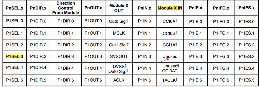
It says unused.
So, is there any problem? My code is below.
/***************************************/
P1DIR&=~BIT4; //P1.4--RX 输入
P1SEL|=BIT4;
P1DIR|=BIT3; //P1.3--TX 输出 第二功能
P1SEL|=BIT3;
void TA1_0_Init()
{
#if 0
TA1CCTL0=CM_2+CCIS_0+SCS+CAP+CCIE; //P1.4---CCI0A
// TA1CCTL0=CM_2+CCIS_1+SCS+CAP+CCIE; //Capture falling edge,P1.3---CCI0B,SCS,捕获模式,中断
#endif
TA1CCR0=OneBit_Time;
TA1CCTL0=OUTMOD_0|OUT;
TA1CTL=TASSEL_2+MC_2; //Source:SMCLK , 连续计数模式
}
/***************************************/
I use the code to test P1.3 output mode,but didn't reach.

