This thread has been locked.

If you have a related question, please click the "Ask a related question" button in the top right corner. The newly created question will be automatically linked to this question.

three low pulse

Other Parts Discussed in Thread: MSP430G2553

Hello ,

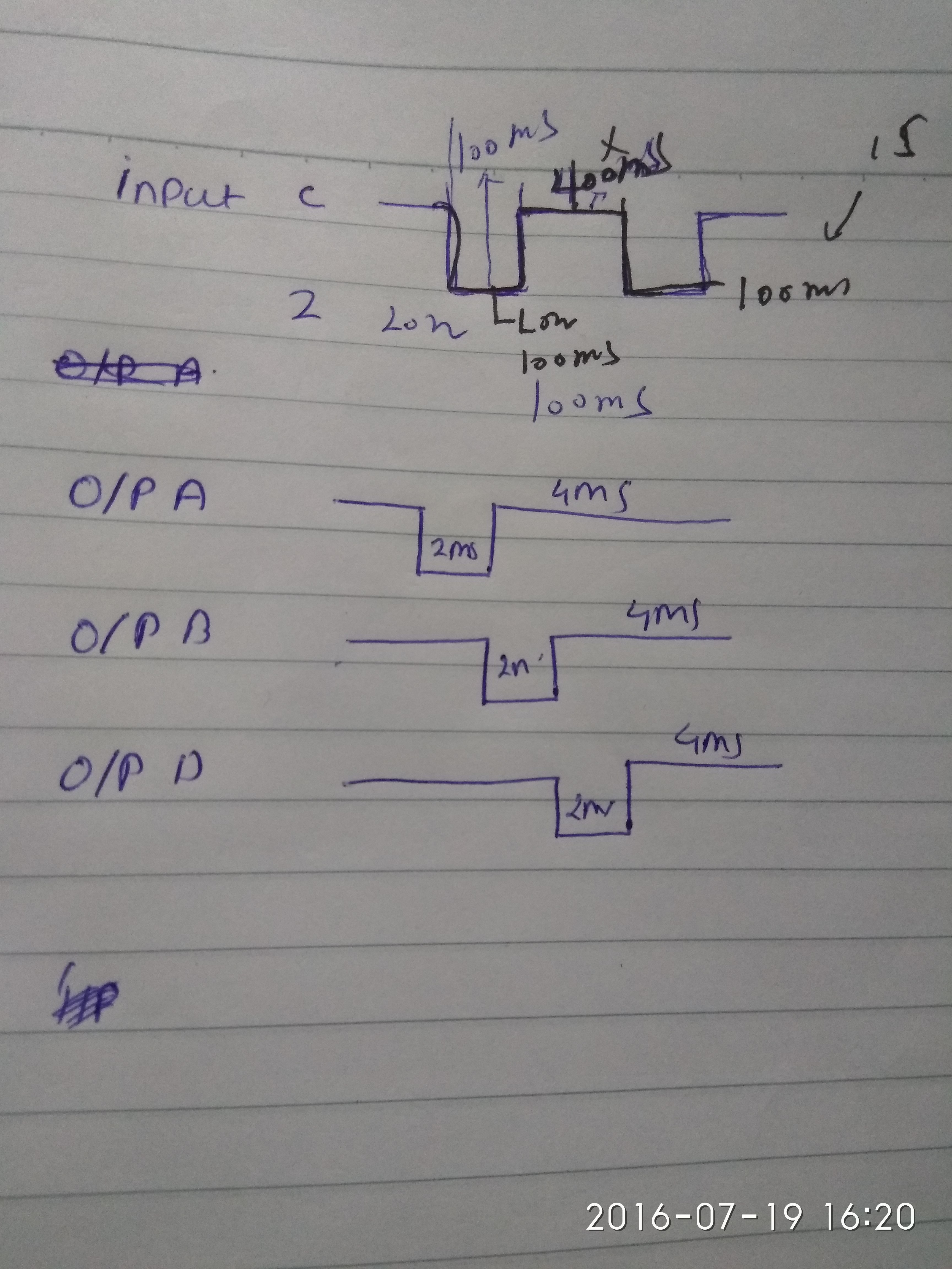
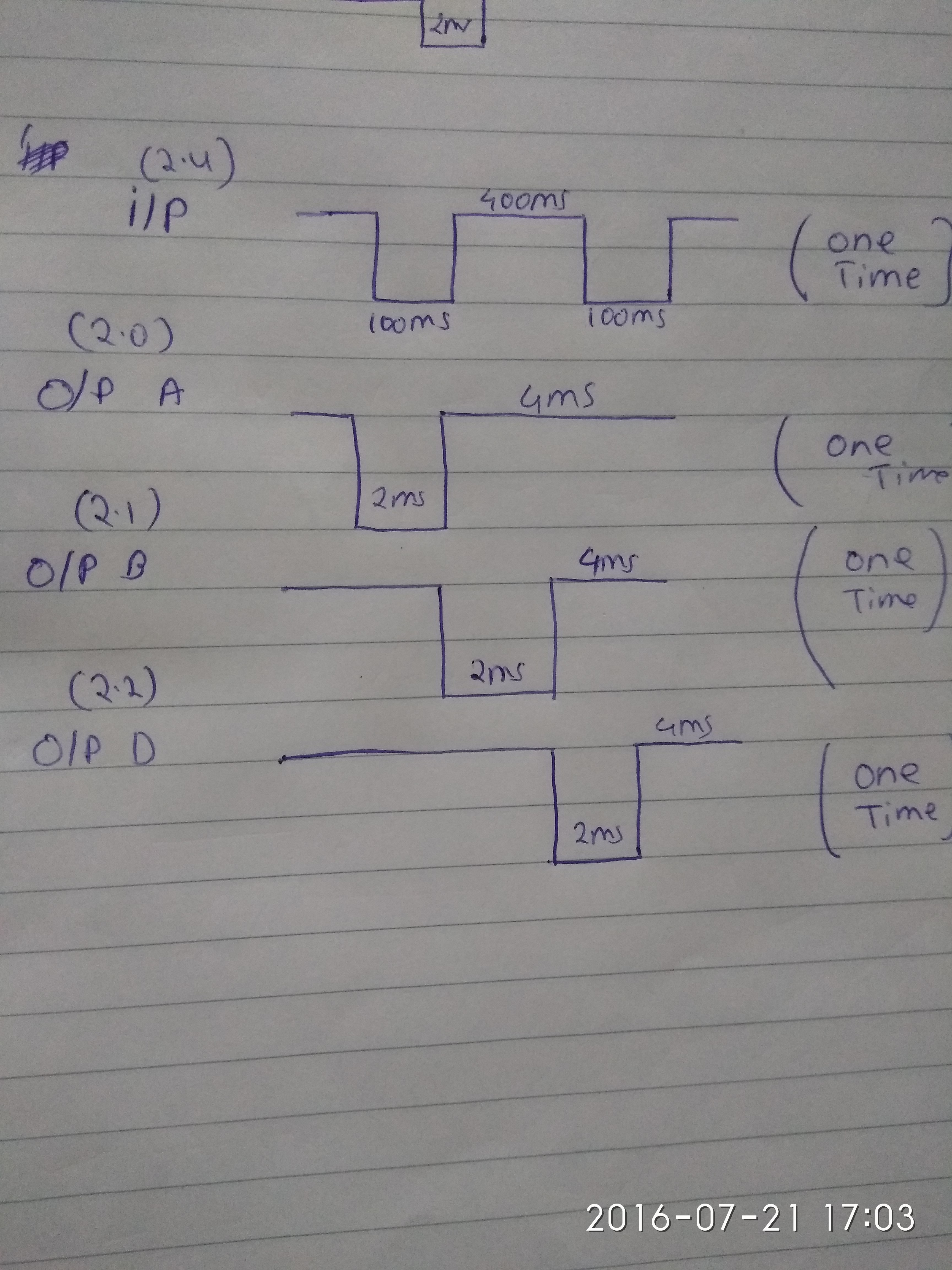
I want to generate this output:

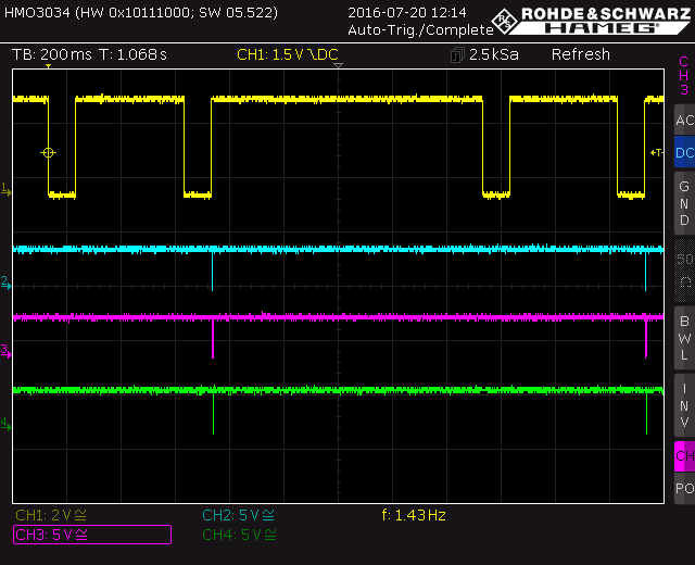
But i am getting this

Here is the code i am pasting, please help me anyone to generate that output :

#include <msp430g2553.h>
#define CPU_F ((double)16000000)
#define delay_us(x) __delay_cycles((long)(CPU_F*(double)x/1000000.0))
#define delay_ms(x) __delay_cycles((long)(CPU_F*(double)x/1000.0))
char C_1, C_2;
void System_Clock_Init( void )
{
    char i;
    _NOP();
    WDTCTL = WDTPW + WDTHOLD;                                         // Close Watching dog
    delay_ms(20);                                                     // 1MHz
    if( ( CALBC1_16MHZ == 0xff ) || ( CALDCO_16MHZ == 0xff ) )        // FLASH A was cleared!!!
        ((void (*)())RESET_VECTOR)();
    BCSCTL1 = CALBC1_16MHZ; //ACLK=32768Hz
    DCOCTL = CALDCO_16MHZ;  //MCLK=DCOCLK=16MHz
    BCSCTL2 = 0x06;//SMCLK=DCOCLK/8=2MHz
    BCSCTL3 = 0x00;//cap=1pF
    IE1 &= ~OFIE;//close crystal error interrupt

    TA0CCR0 =32-1; // PWM Period --> needs to be adjustable
    TA0CCTL1 = OUTMOD_2; // CCR1 reset/set
    TA0CCR1 = CCR0/2; // CCR1 PWM duty cycle 50% -->needs to be adjustable
    TACTL = TASSEL_1 + MC_1; // SMCLK, up mode

    do
    {
        IFG1 &= ~OFIFG;      // 清零SR中的振荡错误标志位OFIFG
        for( i = 0; i < 100; i++ )
        {
            _NOP();
        }
    }
    while (IFG1 & OFIFG);     // 检查OFIFG是否清零

    _NOP();

}

void IO_INIT(void)
{
        P2SEL &= ~BIT4;
        P2SEL2 &= ~BIT4;
        P2REN &= ~BIT4;
        P2DIR &= ~BIT4;
        P2DIR |= BIT2;
        P2IES |= BIT4;
        P2IE  |= BIT4;
        P2IFG  &= ~BIT1;

        P2SEL &= ~(BIT0+BIT1);
        P2SEL2 &= ~(BIT0+BIT1);
        P2REN &= ~(BIT0+BIT1);
        P2DIR &= ~(BIT0+BIT1);
        P2DIR |= (BIT0+BIT1);
        P2OUT &= ~(BIT0+BIT1);

        P2SEL &= ~BIT2;
        P2SEL2 &= ~BIT2;
        P2REN &= ~BIT2;
        P2DIR &= ~BIT1;
        P2DIR |= BIT1;
        P2OUT &= ~BIT2;
}

void main(void)//29uA
{
    System_Clock_Init();
    _NOP();
    //WDTCTL = WDT_ARST_1000;//feed watch dog  ?????下面的程序执行时间???
    _NOP();
    IO_INIT();
    _NOP();
    _EINT();//open all interrupt
    _NOP();
    LPM3;
    _NOP();
    while(1);
}
//------------------------------------------------------------------------------
//Function: Start Timer 0 A0 for Hour Timing 500ms
//------------------------------------------------------------------------------
#pragma vector = PORT2_VECTOR
#pragma vector = TIMER0_A1_VECTOR
__attribute__((__interrupt__(TIMER0_A0_VECTOR)))
void Timer0_A(void)
{
void delay ( unsigned int );

  _NOP();
  delay_us(20);

  if( C_1 == 0xff)
  {
    if(!( P2IN & BIT4 )) C_2 = 0xff;
  }
  else
  {
      if(!( P2IN & BIT4 )) C_1 = 0xff;
  }
  if(( C_1 == 0xff) && ( C_2 == 0xff))
  {
      //output A B D
          P2OUT |= BIT1;
          P2OUT |= BIT2;
          delay_ms(2);
          P2OUT |= BIT1;
          P2OUT &= ~BIT0;
          delay_ms(2);
          P2OUT |= BIT2;
          P2OUT &= ~BIT1;
          P2OUT |= BIT0;
          //delay_ms(2);
          P2OUT &= ~BIT2;
          P2OUT &= ~BIT1;
         // P2OUT |= BIT2;
          delay_ms(2);

        /*  P2OUT |= BIT1;
          P2OUT &= ~BIT2;
          P2OUT |= BIT0;
          //delay_ms(2);*/

          P2OUT ^= BIT1;                 //P2 toggle
          P2IFG &= ~BIT1;                //IFG cleared

          C_1 =0x00;
          C_2 =0x00;
        }
        _NOP();
        }

Output A & B

Output B & D

  • #FreeSampleCode

    #include "msp430G2553.h"
    #include "stdint.h"
    
    
    void main( void )
    {
      WDTCTL = (WDTPW | WDTHOLD);                    // Stop watchdog timer
    
      BCSCTL1 = CALBC1_1MHZ;                         // Set range
      DCOCTL  = CALDCO_1MHZ;                         // Set DCO step and modulation
        
      P2OUT |= (BIT0 | BIT1 | BIT2);                 // P2.0/1/2 high
      P2DIR |= (BIT0 | BIT1 | BIT2);                 // P2.0/1/2 to output direction
    
      TA0CCR0  = 2000;                               // Timer value for 2ms interrupt
      TA0CCTL0 = CCIE;                               // Enable compare interrupt
      TA0CTL   = (TASSEL_2 | ID_0 | MC_2 | TACLR);   // SMCLK, divider 1, continuous mode, clear
    
      __bis_SR_register( GIE );                      // Enable global interrupts
    
      while( 1 )                                     // Main program
      {
    
      }
    }
    
    
    // Timer 0 A0 interrupt service routine
    #pragma vector = TIMER0_A0_VECTOR
    __interrupt void Timer0_A0_ISR( void )
    {
      static uint8_t state = 0;                      // Variable holds actual state
    
      TA0CCR0 += 2000;                               // Timer value for next interrupt in 2ms
    
      switch( state )                                // Determine actual state
      {
        case 0:                                      // State 0
        {
          P2OUT |= BIT2;                             // Set P2.2 high
          P2OUT &= ~BIT0;                            // Set P2.0 low
          break;
        }
    
        case 1:                                      // State 1
        {
          P2OUT |= BIT0;                             // Set P2.0 high
          P2OUT &= ~BIT1;                            // Set P2.1 low
          break;
        }
    
        case 2:                                      // State 2
        {
          P2OUT |= BIT1;                             // Set P2.1 high
          P2OUT &= ~BIT2;                            // Set P2.2 low
          break;
        }
      }
    
      if( ++state >= 3 )                             // Increment state and test if >= 3
      {
        state = 0;                                   // Reset state to 0
      }
    }

  • Very thank you Dennis Eichmann, it's perfectly working.

    These are the output pulse and in this program i have to show the input pulse at one pin.

    in my code pin2.4 is used as input pin and i can't see in the oscilloscope.

    can you help me with this?

    and if you have a time can you look at my code, why i am not getting the output?

    i have attach the pic of the oscilloscope output.

    Thanks

  • Using OUTMOD might not work in your case because for a delayed PWM and three output channels you would need three timer modules, but the MSP430G2553 only has two. Here is an example for two PWMs with a fixed delay:

    But only for two channels.

    Maybe anyone else has another idea.

    Dennis

  • Thanks
    And also i want to see the input pulse from one pin but i can't able to see.
    how can i see input in that?
    in my code i used pin2.4 as a input.
  • What type of input pulse and what shall happen?

  • just like what i am getting in the output, same as i want in the input pin "2 low pulses".
    when input pin produces 2 low pulses then i will get this output.
  • Can you draw a picture of the input and output waveforms and of their dependency?
  • when C receive two low pulses, it produces the output A, B & D.
    I have attached the picture of it.
  • Oh, it is still the water meter thing, right? It would be great if you wouldn't have multiple threads dealing with the same topic. It is a bit confusing.
  • How variable is the timing of your input signal? You should specify a window or minimum/maximum of the high/low signal length.
  • yes, still the water meter thing.
    ok, consider this is the only post. rest thread i will put off that
  • it doesn't have to deal with timing, it's just when input produces two pulse it will give the output A, B & D and nothing else
  • I would say it has to deal with timing - imagine this: One low pulse, pause of ten minutes, another low pulse. Is this still a valid double low pulse?
  • no, because it has pause of ten minutes. one pulse after 400ms another pulse. two pulse in continuation. just 2 pulses
  • There you are - timing is somehow relevant in your case. So you would need a window that specifies a valid pulse to start the output. 400.00000ms high won't be possible. Same for 100ms low.

  • So, can you help me with this? How to generate the input from a pin? Since the program you posted here, giving the correctct output what i want. So it would be nice if you help me how to generate input pulse?

  • Yes, but see my earlier post. I don't know your input signal. You have added a picture saying high -> 100ms low -> 400ms high -> 100ms low -> high, but this won't be possible. How precise are these ms durations? When shall the input be detected as a valid double pulse?
  • Actually it's not that precise and accurate. We can decide about the timings. The thing is to generate 2 low pulse from the input.
  • Singh dushyant Kumar said:
    We can decide about the timings.

    Then this is the time to decide about it.

  • Yes, previously you were saying one pulse and then 10 minutes pause. I think it is good. We will stick to it.
  • Since I do not have your sensor that generates those output pulses, this code is NOT tested:

    #include "msp430G2553.h"
    #include "stdint.h"
    
    
    volatile uint16_t down_counter;                  // Variable for counting down
    volatile uint8_t  output_control = 0;            // Variable controls output activity
    volatile uint8_t  input_state    = 0;            // Variable holds actual input state
    
    
    void main( void )
    {
      WDTCTL = (WDTPW | WDTHOLD);	                 // Stop watchdog timer
    
      BCSCTL1 = CALBC1_1MHZ;                         // Set range
      DCOCTL  = CALDCO_1MHZ;                         // Set DCO step and modulation
    	
      P2REN |= BIT4;                                 // Enable resistor for P2.4
      P2OUT |= (BIT0 | BIT1 | BIT2 | BIT4);          // P2.0/1/2 high, pull-up resistor for P2.4
      P2DIR |= (BIT0 | BIT1 | BIT2);                 // P2.0/1/2 to output direction
      P2IES |= BIT4;                                 // Interrupt on high->low transition
      P2IFG &= ~BIT4;                                // Clear P2.4 IFG
      P2IE  |= BIT4;                                 // Enable interrupts for P2.4
    
      TA0CCR0  = 2000;                               // Timer value for 2ms interrupt
      TA0CCTL0 = CCIE;                               // Enable compare interrupt
      TA0CTL   = (TASSEL_2 | ID_0 | MC_2 | TACLR);   // SMCLK, divider 1, continuous mode, clear
    
      __bis_SR_register( GIE );                      // Enable global interrupts
    
      while( 1 )                                     // Main program
      {
    
      }
    }
    
    
    // Timer 0 A0 interrupt service routine
    #pragma vector = TIMER0_A0_VECTOR
    __interrupt void Timer0_A0_ISR( void )
    {
      static uint8_t output_state = 0;               // Variable holds actual output state
    
      TA0CCR0 += 2000;                               // Timer value for next interrupt in 2ms
    
      if( down_counter )                             // Test if > 0
      {
        down_counter--;                              // Decrement counter
    
        if( !output_control )                        // Test if output is currently off
        {
          if( !down_counter )                        // Test if down counter became 0 now
          {
            input_state = 0;                         // Reset input state
            P2IE  &= ~BIT4;                          // Disable interrupts for P2.4
            P2IES |= BIT4;                           // Interrupt on high->low transition
            P2IFG &= ~BIT4;                          // Clear P2.4 IFG
            P2IE  |= BIT4;                           // Enable interrupts for P2.4
          }
        }
      }
    
      if( output_control )                           // Test if output is active
      {
        switch( output_state )                       // Determine actual output state
        {
          case 0:                                    // State 0
          {
            P2OUT &= ~BIT0;                          // Set P2.0 low
            output_state++;                          // Increment output state
            break;
          }
    
          case 1:                                    // State 1
          {
            P2OUT |= BIT0;                           // Set P2.0 high
            P2OUT &= ~BIT1;                          // Set P2.1 low
            output_state++;                          // Increment output state
            break;
          }
    
          case 2:                                    // State 2
          {
            P2OUT |= BIT1;                           // Set P2.1 high
            P2OUT &= ~BIT2;                          // Set P2.2 low
            output_state++;                          // Increment output state
            break;
          }
    
          case 3:                                    // State 3
          {
            P2OUT |= BIT2;                           // Set P2.2 high
            output_state = 0;                        // Reset output state
            output_control = 0;                      // Reset output control
            P2IFG &= ~BIT4;                          // Clear P2.4 IFG
            P2IE  |= BIT4;                           // Enable interrupts for P2.4
            break;
          }
        }
      }
    }
    
    
    // Port 2 interrupt service routine
    #pragma vector = PORT2_VECTOR
    __interrupt void Port2_ISR( void )
    {
      switch( input_state )                          // Determine actual input state
      {
        case 0:                                      // State 0: High->low transition of first pulse
        {
          down_counter = 60;                         // Timeout of 120ms
          input_state++;                             // Increment input state
          P2IES &= ~BIT4;                            // Interrupt on low->high transition
          break;
        }
    
        case 1:                                      // State 1: Low->high transition of first pulse
        {
          down_counter = 225;                        // Timeout of 450ms
          input_state++;                             // Increment input state
          P2IES |= BIT4;                             // Interrupt on high->low transition
          break;
        }
    
        case 2:                                      // State 2: High->low transition of second pulse
        {
          down_counter = 60;                         // Timeout of 120ms
          input_state++;                             // Increment input state
          P2IES &= ~BIT4;                            // Interrupt on low->high transition
          break;
        }
    
        case 3:                                      // State 3: Low->high transition of second pulse
        {
          P2IES |= BIT4;                             // Interrupt on high->low transition
          output_control = 1;                        // Activate output
          P2IE &= ~BIT4;                             // Disable interrupts for P2.4
          input_state = 0;                           // Reset input state
          break;
        }
      }
    
      P2IFG &= ~BIT4;                                // Clear P2.4 IFG
    }

    If it doesn't work as expected, try to debug it.

    Dennis

  • thanks for the code.

    the code you posted here doesn't contains any error but i am not getting any output pulse from any pins.
    oscilloscope showing nothing.

    it's just the lines in the oscilloscope going up and down.

  • It shall output one burst of pulses after receiving the valid input signal. But as I said: not tested. You can now start to debug it.
  • i have started debugging but can't able to generate the output. modifying the code, still no results.
  • What happens after an input signal? Does the port 2 interrupt occur?
  • no, port2 interrupt doesn't occur.
  • How do you know for sure?
  • because when i checked the output, still not showing anything
  • This doesn't say anything about the interrupt. Set a breakpoint inside the ISR and look if it gets hit.
  • i put the break point in line 47, it says "remain halted" and also in line 54 (separately), it remains halted
  • Why in line 47 or 54?
  • sorry, i put in 118 and 120, port 2 ISR, "remain halted"
  • If you use > Run To Line <?
  • I double click on that line to make it breakpoint and then debug to see the interrupt
  • Then try to use > Run To Line < (Strg + R)
  • sorry i didn't get, what's this "> Run To Line < (Strg + R)" ?
    can you briefly tell me about it?
  • The IDE has a function called "Run To Line" - you set the cursor at the line you want the program to stop and the program will execute until it hits this line.
  • i am using code composer studio 6, so i didn't see that option. it has step over or step into functions
  • i will explain you more about the input is that, when i connect to input pin, the output will be just high line i.e. A, B&D will be just high line. After input gets 2 pulse than A, B&D will become pulse. Ans also i don't want the train of the pulse, i want just one pulse.
    It's like, when input is connected A, B&D must be a high line, after getting two pulses from input, the output will be one pulse, just one pulse not train of pulse.
  • Yes, you want 1 burst of the output, this is what I understood.

  • Singh, it would be great if you would read this, especially item no. 4, paragraph 4 ("Solving your problem means...").

    Dennis

  • Hi Singh!

    I now added some code to emulate your sensor output - I did not change anything on the code I posted before.

    The emulated sensor now outputs:

    1s high (pause) -> 100ms low -> 400ms high -> 100ms low -> 1s high (pause) -> 100ms low -> ...

    You said that this is the signal from your sensor output. Here you can see the waveform - the yellow one is the emulated output:

    Blue, purple and green are P2.0, P2.1 and P2.3 - if you zoom into the picture you will see the following:

    This means the software behaves exactly like you wanted. Two low pulses cause one reaction on the three outputs. Then a pause of 1s, followed by the next input and output.

    Here is the code:

    #include "msp430G2553.h"
    #include "stdint.h"
    
    
    volatile uint16_t down_counter;                  // Variable for counting down
    volatile uint8_t  output_control = 0;            // Variable controls output activity
    volatile uint8_t  input_state    = 0;            // Variable holds actual input state
    
    
    void main( void )
    {
      WDTCTL = (WDTPW | WDTHOLD);	                 // Stop watchdog timer
    
      BCSCTL1 = CALBC1_1MHZ;                         // Set range
      DCOCTL  = CALDCO_1MHZ;                         // Set DCO step and modulation
    	
      P2REN |= BIT4;                                 // Enable resistor for P2.4
      P2OUT |= (BIT0 | BIT1 | BIT2 | BIT4);          // P2.0/1/2 high, pull-up resistor for P2.4
      P2DIR |= (BIT0 | BIT1 | BIT2);                 // P2.0/1/2 to output direction
      P2IES |= BIT4;                                 // Interrupt on high->low transition
      P2IFG &= ~BIT4;                                // Clear P2.4 IFG
      P2IE  |= BIT4;                                 // Enable interrupts for P2.4
    
      TA0CCR0  = 2000;                               // Timer value for 2ms interrupt
      TA0CCTL0 = CCIE;                               // Enable compare interrupt
      TA0CTL   = (TASSEL_2 | ID_0 | MC_2 | TACLR);   // SMCLK, divider 1, continuous mode, clear
    
      // Input emulation
      P1OUT |= BIT0;                                 // P1.0 high
      P1DIR |= BIT0;                                 // P1.0 output - emulates output of sensor
    
      TA1CCR0  = 62500;                              // Timer value for 500ms interrupt
      TA1CCTL0 = CCIE;                               // Enable compare interrupt
      TA1CTL   = (TASSEL_2 | ID_3 | MC_2 | TACLR);   // SMCLK, divider 8, continuous mode, clear
      // Input emulation
    
      __bis_SR_register( GIE );                      // Enable global interrupts
    
      while( 1 )                                     // Main program
      {
    
      }
    }
    
    
    // Input emulation
    // Timer 1 A0 interrupt service routine
    #pragma vector = TIMER1_A0_VECTOR
    __interrupt void Timer1_A0_ISR( void )
    {
      static uint8_t timer_state = 0;                // Variable holds actual timer state
      static uint8_t multiplier  = 0;                // Variable to extend timer interval
    
      switch( timer_state )                          // Determine actual timer state
      {
        case 0:                                      // Delay between pulses
        {
          if( ++multiplier < 2 )                     // Not 1s elapsed yet
          {
            TA1CCR0 += 62500;                        // Add 500ms
          }
          else                                       // 1s elapsed
          {
            TA1CCR0 += 12500;                        // Add 100ms
            P1OUT &= ~BIT0;                          // P1.0 low
            multiplier  = 0;                         // Reset multiplier
            timer_state++;                           // Increment timer state
          }
    
          break;
        }
    
        case 1:                                      // Signal was low for 100ms
        {
          TA1CCR0 += 50000;                          // Add 400ms
          P1OUT |= BIT0;                             // P1.0 high
          timer_state++;                             // Increment timer state
    
          break;
        }
    
        case 2:                                      // Signal was high for 400ms
        {
          TA1CCR0 += 12500;                          // Add 100ms
          P1OUT &= ~BIT0;                            // P1.0 low
          timer_state++;                             // Increment timer state
    
          break;
        }
    
        case 3:                                      // Signal was low for 100ms
        {
          TA1CCR0 += 62500;                          // Add 500ms
          P1OUT |= BIT0;                             // P1.0 high
          timer_state = 0;                           // Reset timer state
    
          break;
        }
      }
    }
    // Input emulation
    
    
    // Timer 0 A0 interrupt service routine
    #pragma vector = TIMER0_A0_VECTOR
    __interrupt void Timer0_A0_ISR( void )
    {
      static uint8_t output_state = 0;               // Variable holds actual output state
    
      TA0CCR0 += 2000;                               // Timer value for next interrupt in 2ms
    
      if( down_counter )                             // Test if > 0
      {
        down_counter--;                              // Decrement counter
    
        if( !output_control )                        // Test if output is currently off
        {
          if( !down_counter )                        // Test if down counter became 0 now
          {
            input_state = 0;                         // Reset input state
            P2IE  &= ~BIT4;                          // Disable interrupts for P2.4
            P2IES |= BIT4;                           // Interrupt on high->low transition
            P2IFG &= ~BIT4;                          // Clear P2.4 IFG
            P2IE  |= BIT4;                           // Enable interrupts for P2.4
          }
        }
      }
    
      if( output_control )                           // Test if output is active
      {
        switch( output_state )                       // Determine actual output state
        {
          case 0:                                    // State 0
          {
            P2OUT &= ~BIT0;                          // Set P2.0 low
            output_state++;                          // Increment output state
            break;
          }
    
          case 1:                                    // State 1
          {
            P2OUT |= BIT0;                           // Set P2.0 high
            P2OUT &= ~BIT1;                          // Set P2.1 low
            output_state++;                          // Increment output state
            break;
          }
    
          case 2:                                    // State 2
          {
            P2OUT |= BIT1;                           // Set P2.1 high
            P2OUT &= ~BIT2;                          // Set P2.2 low
            output_state++;                          // Increment output state
            break;
          }
    
          case 3:                                    // State 3
          {
            P2OUT |= BIT2;                           // Set P2.2 high
            output_state = 0;                        // Reset output state
            output_control = 0;                      // Reset output control
            P2IFG &= ~BIT4;                          // Clear P2.4 IFG
            P2IE  |= BIT4;                           // Enable interrupts for P2.4
            break;
          }
        }
      }
    }
    
    
    // Port 2 interrupt service routine
    #pragma vector = PORT2_VECTOR
    __interrupt void Port2_ISR( void )
    {
      switch( input_state )                          // Determine actual input state
      {
        case 0:                                      // State 0: High->low transition of first pulse
        {
          down_counter = 60;                         // Timeout of 120ms
          input_state++;                             // Increment input state
          P2IES &= ~BIT4;                            // Interrupt on low->high transition
          break;
        }
    
        case 1:                                      // State 1: Low->high transition of first pulse
        {
          down_counter = 225;                        // Timeout of 450ms
          input_state++;                             // Increment input state
          P2IES |= BIT4;                             // Interrupt on high->low transition
          break;
        }
    
        case 2:                                      // State 2: High->low transition of second pulse
        {
          down_counter = 60;                         // Timeout of 120ms
          input_state++;                             // Increment input state
          P2IES &= ~BIT4;                            // Interrupt on low->high transition
          break;
        }
    
        case 3:                                      // State 3: Low->high transition of second pulse
        {
          P2IES |= BIT4;                             // Interrupt on high->low transition
          output_control = 1;                        // Activate output
          P2IE &= ~BIT4;                             // Disable interrupts for P2.4
          input_state = 0;                           // Reset input state
          break;
        }
      }
    
      P2IFG &= ~BIT4;                                // Clear P2.4 IFG
    }

    P1.0 was used to emulate the sensor output, now directly connected to P2.4. Since I changed nothing on the code, I have to ask if you are sure about the sensor output? Maybe you have to test if the code behaves as expected (reset the detection mechanism) when the input is different or disturbed. I did not do that here.

    Dennis

  • Yes, i am sure about the sensor output. When input has 2 low pulse, the outputs behaves like this. Basically at first when input is connected, the output will be straight line. After some seconds or some time when input will produce 2 pulse in burst mode (no train of pulse) then 3 output pulse will be on the screen that too one pulse (burst mode).
  • So what does that mean? Does it work or not? How is it possible that the interrupt does not occur on your hardware? If you have an output, then the interrupt must have fired.
  • In the zoom picture what i see is when emulatd output is low, the 3 outputs are also low. Am i right?
  • Where do you see this?!
  • Ok, ok. I will check on my hardware and oscilloscope and i will let you know about this.
  • This makes me thinking that you did not even try/test anything at your place yet. I think I'm out here.

    Dennis
  • No no, don't think like that. Whatever you have said i have tried. Don't be angry. And don't be out of this. Please. I was  little outside my place, that's why .

    So please be with me and don't be out of this.

    I will let you know about this.

  • I think this guy needs a good on-site tutor, sitting next to him. There are too much of the basics missing. Forum-based attempts use to end in frustration on both (multiple) sides.
    That's wy I use to stay away from those threads ...

**Attention** This is a public forum