This thread has been locked.

If you have a related question, please click the "Ask a related question" button in the top right corner. The newly created question will be automatically linked to this question.

msp430F6733: How to demonstrate ILPM4=1.6uA ? (Schem and Firmware)

Other Parts Discussed in Thread: MSP-TS430PZ100B, ENERGYTRACE, MSP-FET, EVM430-F6736

Hello,

Could you please advice how to demonstrate  ILPM4=1.6uA ?

Let me explain my status:

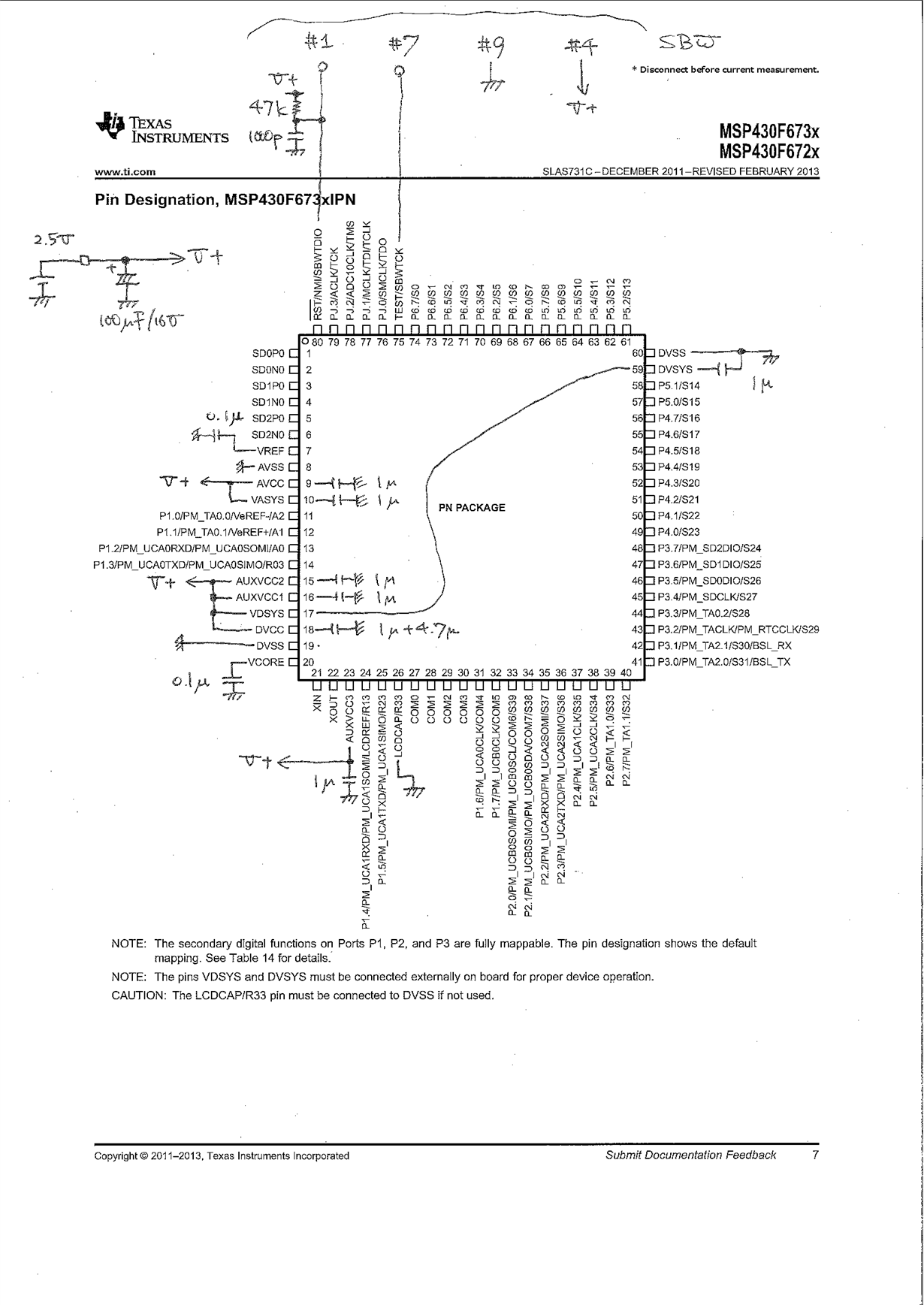
- I built a board as the attached schem

- The sample code "MSP430F673X_LPM4.c" was executed.

>>> The measured board supply current  was 3.1uA @ Vs=3.0Volts.

[Schematic]

Therefore, If you recommend the sample board MSP-TS430PZ100B, please instruct the proven JP settings or additional wirings.

Your correction to my schem is also appreciated if you find anything.

[Firmware]

Please tell me if we need to edit "MSP430F673X_LPM4.c" to see 1.6uA.

-n

  • Hi Hideaki,

    How are you measuring the current consumption? Which debugger are you using? Are there any other components on your board that could be influencing this measurement?

    To accurately measure the current consumption, I'd recommend using EnergyTrace in CCS. The MSP-FET supports the EnergyTrace feature for all MSP430 devices. If your board doesn't include a JTAG header that matches the MSP-FET connector, it may be easier to use the target board, which does. To use either 2-wire or 4-wire JTAG on the target board, you just need to move the jumpers according to what's shown on the silk screen (e.g. SBW or JTAG).

    Regarding your schematic, here are some general comments/recommendations:

    • The supply voltage capacitance of 100 uF is more than the typical 10 uF, but this may be necessary if you have other components on the rail. However, if the MSP-FET is ever used to power the board, please keep in mind that capacitance larger than 10 uF may cause an inrush current during capacitor charging that may exceed 60 mA, which is the maximum allowed current consumption of the target.
    • For the SBW JTAG interface, you'll want to implement the proper signal connections if you plan on using the MSP-FET. Also, for decoupling purposes, you'll want to have 0.1 uF capacitors at the VCC/AVCC/DVCC pins.

    • I see that you've connected VDSYS and DVSYS together and also LCDCAP pin tied to DVSS, which is good.
    • Depending on your application and whether or not the analog inputs will be used, you may want to consider separating your digital (DVCC) and analog (AVCC) supplies and grounds. The schematic for the EVM430-F6736 on page 26 in this app note shows this configuration along with different capacitor values on VCORE, VASYS, VDSYS, AUXVCCx, etc. It's an excellent reference. Some of these values are defined on page 61 in the datasheet.
    • Based on the table and footnotes 4 and 8 for LPM4 mode on page 49 in the datasheet, try making sure that the default PMMCOREVx values are at 0 or 1 and that the high side monitor is disabled (SVMH) and RAM retention is enabled.

    Let me know if this helps.

    Regards,

    James

    MSP Customer Applications

  • James, thank you for your response.

    The current decreased when the SVSMHCTL.SVSHE was kept to one. Could you please tell me the reason ?

    "MSP430F673X_LPM4.c" Line-82

    >>>>

    #if 1 // edit to keep SVSHE=1.

       SVSMHCTL &= ~(SVMHE        );           // 1.2uA ### Good!

    #else // original code.

       SVSMHCTL &= ~(SVMHE | SVSHE);           // 3.1uA

    #endif

    <<<<

    ==========

    Responses to your post:

    J> How are you measuring the current consumption?

    n> A handy tester current meter was inserted between the positive side of the 2.5V supply and the cap 100uF/16V.

    J> Which debugger are you using?

    n> MSP-FET. Please noted the FET was connected only for programming. FET removed for curent measurements.

    J> Are there any other components on your board that could be influencing this measurement?

    n> Just the current meter,

    J> Energy trace

    n> I'm sorry, Today I could not launch. The board has the SBW port, but does it work to evaluate LPM4 current ?

    J> Based on the table and footnotes 4 and 8 for LPM4 mode on page 49 in the datasheet, try making sure ..

    n> Yes, The footnotes 4 instructs to enable the SVSH. This was the key to reduce the current consumption.

  • In Footnote 4, it mentions that "current for brownout, high side supervisor (SVSH) normal mode is included" inferring that SVSHE is kept at one here. Looking at the Backup Subsystem section on page 26 in the datasheet, it says that "it is necessary to keep the high side SVS enabled ... to turn off the low-frequency oscillator (XT1) in LPM4". Perhaps, this is the reason.

    Regarding EnergyTrace, you can launch it independently of a debug session in CCS to measure LPM4 current with the MSP-FET.

    Regards,

    James

    MSP Customer Applications

  • James,

    Thank you for your response. Very clear.

    The sample code "MSP430F673X_LPM4.c" would be better to be revised for our best experience ..

    Conclusion:

    - The sample code "MSP430F673X_LPM4.c" Line-82 should be edited to keep SVSHE=1, like,

    SVSMHCTL &= ~(SVMHE        );

    - No problems in the schematic.

  • Hi Hideaki,

    Thank you for your feedback. I've passed it along to our software team.

    Regards,

    James

    MSP Customer Applications

**Attention** This is a public forum