This thread has been locked.

If you have a related question, please click the "Ask a related question" button in the top right corner. The newly created question will be automatically linked to this question.

Connecting the MSP430G2452IPW20 to CCS (V6.1.3)

Other Parts Discussed in Thread: MSP-TS430PW28A, MSP430G2452, ENERGIA

Hello,

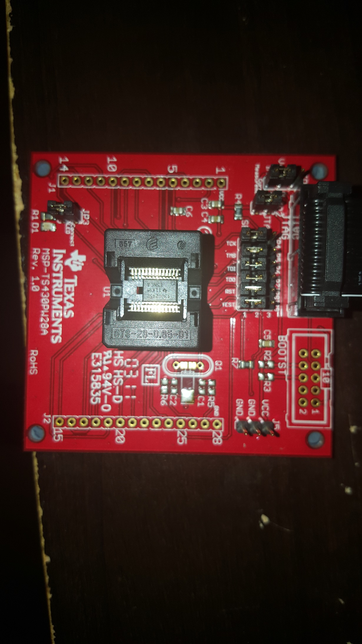
When trying to connect the MSP430G2452IPW20 microcontroller to the CCS using MSP-TS430PW28A I get an error when trying to debug my program that says "Error connecting to the target: Unknown device."  I am simply using the standard blink the LED example code that is provided in CCS.  When creating the whole project, I put in the family MPS430G2XXX and the target as MSP430G2452 because there isn't an option for MSP430G2452IPW20.  Is there something that I am doing wrong here?  I have all of the jumpers on the development board (the msp-ts430pw28A) set for debugging and power from the JTAG port and I am using the MSP-FETFlash Emulation Tool to connect the development board to my laptop.  I also have not downloaded any add on software packages is that needed?  Any suggestions for what I am doing wrong is greatly appreciated.  Thanks

  • Hello Michael,

    You've described a compatible setup, the issue is not centered around any software or FET used but rather the physical connection itself, particularly concerning the Vcc, GND, and JTAG/SBW lines. Please confirm that pin 1 of the device correctly matches the target board's indicator since the EVM can hold a device with more pins than currently needed. Also make sure that the Vcc jumper (JP1) is set to int, that the current measurement jumper (JP2) is shorted, and that JP4 through JP9 are all populated either on JTAG or SBW.

    Regards,
    Ryan
  • Thanks for the reply I have the following configuration:
    JP1 connected to VCC and int
    JP2 & JP3 have jumpers on them
    JP4- JP9 all have a jumper connecting pins 2&3 or connected to JTAG
    Could the problem lie with the J5 jumpers? The description says its for external power so when I have the jumper between VCC & GND I get a message saying I need a firmware update but it never updates. Between GND & GND gives the same cannot connect message. Any Suggestions to fix this?
  • Sorry for not including this. I saw on some other forum posts that you can just ignore the firmware updates in some cases, however, in mine I just get an error saying cannot initialize the VCC voltage
  • Nothing should be connected to J5, these are header pins as compared to jumper pins. The rest of your settings appear to be fine, you may want to try SBW instead of JTAG to see if this makes a difference. Have you ensured that the device is locked into the connector properly? Can you provide an image of your target board with the device attached?
  • Im actually assuming the problem is because I didn't solder the pins onto the left and right side of the board.  When looking at the schematic I didn't think that was needed.  Is that the problem?

  • No, you do not need to solder pins on the left and right side of the board. The MSP430G2452 is locked into the connector, correct? As in you push down on the connector, place the MCU IC, and then release the connector to lock in the unit? Please verify the Vcc voltage and measure the RST and TEST lines with an oscilloscope if possible.

    Regards,
    Ryan
  • Ryan,

    The MSP430G2452 is properly locked into place. As you said, when I insert the MCU I push down on the connector, place the MCU in the right place corresponding to pin 1 (The upper left most pin, where there is a small circle above). Then I release the connectors and the MCU is securely in place. After measuring the voltage I got a value of roughly 3.3V for Vcc, RST, and TEST. As of now I am uninstalling CCS and going to try and reinstall, maybe I missed something going through this process the first time. Please let me know if you have any other suggestions, if talking on the phone is easier I could email you and provide you with my information.

    Thanks,

    Mike
  • Mike,

    How long is the JTAG connector cable? Have you tried any other MSP430G2452 devices? Has this target board properly programmed a different MSP430? No doubt that the MSP430G2452IPW20 is supported by the MSP-TS430PW28A (from the Hardware Tools User's Guide, SLAU278): www.ti.com/.../slau278y.pdf

    I still don't think software is the issue but at this point I suppose that it's worth a shot. I would also recommend trying the IAR or Energia IDEs.

    Regards,
    Ryan
  • The JTAG ribbon connector cable is approximately 6in. I have 2 of the same MSP430G2452 and both of them are having the same error. I will look into downloading the IAR and Energia IDEs, however, I have a Mac and I don't know if those are compatible. Is there any tests you know of that I can before to see if these MCUs are burnt out or damaged?
  • Does there exist some previous indication that these units are damaged? Are the MCUs brand new out-of-box? I doubt these units have been compromised. You may also try testing with a Windows OS.

    Regards,
    Ryan

**Attention** This is a public forum